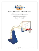
background image


JSL-Inst039 

www.jayprosports.com


J

AYPRO 

ELITE


S

ERIES 

A

DJUSTABLE 

P

ORTABLE 

B

ACKSTOPS


Installation and Operating Instructions


Applicable Part Numbers/Models: 

PBEL54:  Jaypro Elite 5400 
PBEL66:  Jaypro Elite 6600 
PBEL96:  Jaypro Elite 9600 


Содержание Elite Series

Страница 1: ...w jayprosports com JAYPRO ELITE SERIES ADJUSTABLE PORTABLE BACKSTOPS Installation and Operating Instructions Applicable Part Numbers Models PBEL54 Jaypro Elite 5400 PBEL66 Jaypro Elite 6600 PBEL96 Jay...

Страница 2: ...ize 42 X 72 Glass Goal Type GBA 18042 Edge Pad MBBP 6 Wheels 8 Diameter 2 Thick non marking Features Front foot leveling Easy one person setup height adjustment Pin stop adjustments at 6 increments be...

Страница 3: ...X 72 Glass Goal Type GBA 18042 Edge Pad MBBP 6 Wheels 8 Diameter 2 Thick non marking Features Front foot leveling Easy one person setup height adjustment Pin stop adjustments at 6 increments between...

Страница 4: ...board Size 42 X 54 Glass Goal Type GBA 542 Edge Pad MBBP 54 Wheels 8 Diameter 2 Thick non marking Weight 1600 lbs Features Front foot leveling Easy one person setup height adjustment Pin stop adjustme...

Страница 5: ...s Hardware 4 5 2 Locator Kit 4 5 3 Anchor Kit PBELKIT 4 5 4 Backboard 5 5 5 Backboard hardware kit 5 5 6 Rim 6 6 Installing Backboard Rim 6 7 Unpacking 12 8 Set Foot Stops 13 9 Padding Installation 16...

Страница 6: ...lied quick release pin Unit must be pinned in position using supplied quick release pin at all times unless raising or lowering When raising or lowering do not release handles unless backstop is pinne...

Страница 7: ...ibed in sections 1 through 10 Section 11 describes the procedure for raising and lowering the backstop and is intended to be used by the end user Section 12 describes the procedure for adjusting the l...

Страница 8: ...tup If any of the following items are missing contact the Jaypro Sports customer support team Monday through Friday 8 30AM to 5 00 PM EST at 1 800 243 0533 5 1 Miscellaneous Hardware Figure 5 1 Quick...

Страница 9: ...e 5 9 Backboard 72 board supplied w PBEL96 PBEL 66 54 with PBEL54 Figure 5 10 Left viewed from court backboard support arm 1X Figure 5 11 Right viewed from court backboard support arm 1X 5 5 Backboard...

Страница 10: ...5 23 3 8 16 Flanged Hex Nuts 4X Figure 5 24 3 8 Flat Washer 4X Figure 5 25 3 8 Split Washer 4X Figure 5 26 3 8 x 3 3 4 Hex Bolt 4X 6 Installing Backboard Rim WARNING DO NOT REMOVE SAFETY STRAP OR QUIC...

Страница 11: ...supplied socket wrench Figure 6 2 Lower feet until bottom horizontal 2 x 4 s are level 2 Attach left and right backboard support arms to slots in boom using the 5 16 18 x 3 4 carriage bolts 2X 5 16 fl...

Страница 12: ...ers 2X into middle row of holes in backboard mount Figure 6 5 details A B 5 Slide the bolts in step 4 into the middle set of holes of the backstop boom Fasten bolts to boom using the 3 8 flat washers...

Страница 13: ...en rim to board using the 3 8 16 x 3 hex bolts 4X 3 8 flat washers 8X 3 8 split washers 4X and 3 8 flanged nuts 4X as shown in Figure 6 6 Ensure that rim is level side to side4 before fully tightening...

Страница 14: ...ELITE Series Adjustable Portable Backstop Instructions 10 of 27 JSL Inst039 www jayprosports com Figure 6 5 Installation of backboard to boom...

Страница 15: ...ELITE Series Adjustable Portable Backstop Instructions 11 of 27 JSL Inst039 www jayprosports com Figure 6 6 Attach rim to board...

Страница 16: ...kle release a Pay extra attention when removing the strap to make sure that the backstop does not begin to rise on its own If it does retighten strap reinstall the quick release pin and refer to secti...

Страница 17: ...PLIED QUICK RELEASE PIN WARNING UNIT MUST BE PINNED IN POSITION USING SUPPLIED QUICK RELEASE PIN AT ALL TIMES UNLESS RAISING OR LOWERING WARNING WHEN RAISING OR LOWERING DO NOT RELEASE HANDLES UNLESS...

Страница 18: ...le on lower upright 4 Raise backstop to maximum height the uprights will reach a hard stop and will be fully vertical c Insert the quick release pin into the height adjuster 5 Verify that the top of t...

Страница 19: ...hanism CAUTION Once the foot stops are set never apply excessive force when raising or lowering the feet If too much resistance is encountered remove the front padding and verify that the foot stops h...

Страница 20: ...m 9 Padding Installation Padding should be installed after the foot stops have been set see section 8 above 9 1 Included Padding Figure 9 1 Front Pad 1X Figure 9 2 Side Pads 1X Right 1X Left PBEL54 PB...

Страница 21: ...20X 9 2 Padding Installation 2 Install the left and right side pads a Properly locate the side pads by aligning the holes on the inside faces of the pads with the hubs on the sides PBEL base frame Fi...

Страница 22: ...feet until the front wheels are on the ground b Support the front pad against the front of the base frame such that the top is flush with the tops of the side pads Use of 1 4 3 8 shim is recommended c...

Страница 23: ...rk the locations for the L Clips on the rear of the front pad according to the diagram below Figure 9 11 Figure 9 11 Location of holes for J L Clips b Fasten the L Clips to the rear of the front pad a...

Страница 24: ...x4 s d Slide the pad downward until the L Clips are ftted securely over the top 2x4 e Secure the front pad to the bottom front 2x4 with two u brackets 5 Install the top pad PBEL66 PBEL96 6 a Slide the...

Страница 25: ...ered on court and the front surface padding removed is the correct distance from the baseline see figure below distance varies depending on model b Use the transfer punch to locate holes for locator b...

Страница 26: ...ELITE Series Adjustable Portable Backstop Instructions 22 of 27 JSL Inst039 www jayprosports com Figure 10 1 PBEL54 Locating and anchor holes Figure 10 2 PBEL66 Locating and anchor holes...

Страница 27: ...ELITE Series Adjustable Portable Backstop Instructions 23 of 27 JSL Inst039 www jayprosports com Figure 10 3 PBEL96 Locating and anchor holes...

Страница 28: ...L INJURY AS WELL AS SIGNIFICANT DAMAGE TO SURROUNDING STRUCTURES 11 1 Raising Backstop 1 Roll backstop into position such that the locator holes are directly above the locator bushings in the floor 2...

Страница 29: ...kstop is fully lowered a Always stand on the same side of the unit as the ring on the quick release pin when pulling the pin never reach across to the other side of the upright to pull the pin b See F...

Страница 30: ...pin form the height adjuster mechanism to see if the problem has been corrected If not repeat steps a and b 4 If the unit requires excessive force to raise the springs do not have enough pre tension...

Страница 31: ...lecheck that the board and rim are level and plumb and verify that all bolted connections are well fastened If you require additional information or support maintaining your backstops please contact t...

Отзывы: