background image

-  16  -

We thank you for having purchased this power tool that will 

hereafter also be referred to as “angle grinder”.

 IMPORTANT! The angle grinder is suitable, when used 

with the appropriate discs, for the grinding, sanding, wire 

brushing, polishing and abrasive cutting of materials such 

as metal, wood, plastic and dry bricks.

It is prohibited to use dangerous materials in environments 

with risk of fire/explosion.

These instructions contain information deemed necessary for 

proper use, knowledge and standard tool maintenance. It does 

not provide information on the processing techniques on various 

materials; the user will find more information in specific books 

and publications or by taking part in training courses.

COMPONENTS

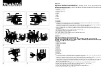
Refer to fig. A and the following figures, attached to these 

instructions.

1.  Power supply plug and cable

2.  Main handgrip

3.  Start/stop switch

4.  Safety immobiliser device (where fitted)

5.  Disc holder shaft lock button

6.  Gear box

7.  Disc holder shaft

8.  Disc holder flange

9.  Disc lock flange

10.Abrasive disc (not included)

11.Disc locking key

12.Seat for lateral handgrip

13.Side handgrip

14.Guard

15.Air vents

16.Handgrip rotation device (where fitted)

17.Power voltage LED (where fitted)

18.Speed regulator (where fitted)

19.Polish/grind plate (where fitted)

20.Abrasive paper discs (where fitted)

21.Fabric disc for polishing (where fitted)

22.Circular brush (where fitted)

23.Revolving brush locking key (where fitted)

24.Protection fixing flange and screws

25.Protection fixing screw

INSTALLATION

 IMPORTANT! The manufacturer is not liable for any direct 

and/or indirect damage caused by incorrect connections.

 IMPORTANT! Before carrying out the following operations, 

make sure that the plug is disconnected from the mains.

TRANSPORT

Always use the packaging or case (when provided) when 

transporting the tool; this will protect it from impact, dust and 

humidity which can compromise normal operation.

During transport, remove the abrasive disc, brush, etc. from 

the machine.

HANDLING

Firmly grasp the handgrip (pos. 2) without using the switch; 

keep the tool well away from your body and after use place it 

down gently without hitting the disc.

STARTING UP

When choosing where to use the power tool, the following 

should be considered:

-  that the area is not damp and is sheltered from the elements.

-  that the working area is sufficiently large and free from obstacles.

-  that the area is well lit.

-  that the tool is used close to the interrupter switch.

-  that the power supply system is earthed and conforms to the 

standards (only if the power tool is Class 1, and equipped with 

a plug with earth cable).

-  that the room temperature should be between 10° and 35° C.

- that the environment is not in a flammable/explosive atmo-

sphere.

Take out the machine and components and visually check that 

they are perfectly intact; then proceed to thoroughly clean them 

in order to remove any protective oils from metal surfaces.

ASSEMBLING PROTECTION PROVIDED WITH THE ANGLE 

GRINDER (fig.C, pos.10)

 IMPORTANT! Only certain types of abrasive discs can 

be installed on a given protection; follow the information 

provided in the “INSTRUCTIONS - Disc Protection” chapter 

on the following pages.

Protection already assembled on the angle grinder:

Check that the protection has been correctly assembled and 

fixed.

Disassembled protection provided:

Depending on the protection in use, follow the relevant steps 

below.

Protection secured with a flange (pos.24):

Turn the angle grinder upside down. Unscrew the disc lock 

flange (pos.9) and remove the disc hold flange (pos.8) from 

the threaded shaft (pos.7). Unscrew the screws securing 

the flange (pos.24) and remove it. Mount the protection 

(pos.14) on the angle grinder, inserting it in the circular 

seat. Reposition the flange on the protection and tighten the 

screws using the washers, but do not secure completely. 

Rotate the protection into the position indicated in fig.A 

(protection turned towards the main handgrip) and secure 

the screws tightly.

Protection secured with a single screw (pos.25):

Turn the angle grinder upside down. Mount the protection 

(pos.14) on the angle grinder, inserting it in the circular 

seat. Rotate the protection into the position indicated in fig.A 

(protection turned towards the main handgrip). Secure by 

tightening the screw located on the ring. Make sure that it 

is firmly locked into place and does not turn.

SIDE HANDGRIP ASSEMBLY (pos.13)

The lateral handgrip can be assembled on any side on which 

there is a threaded hole (pos.12); it is usually secured on the left 

in order to grab hold with the left hand, but it can be assembled 

in the position of your preference (e.g. for left-handed people). 

Insert the handgrip into the threaded hole of the device and 

secure by screwing tightly.

ABRASIVE DISC ASSEMBLY (pos.10, not included)

1) Check that the rotation direction of the disc corresponds to 

that of the angle grinder.

2) Turn the angle grinder upside down.

3) Check that the diameter of the seat of the 2 flanges and the 

hole of the disc are the same size; to this end, it is better 

to measure using a gauge (not included) and reading the 

technical data.

4) Temporarily block the rotation of the motor shaft by pressing 

the button (pos.5) and unscrew the disc lock flange (pos.9). 

Do not disassemble the disc hold flange (pos.8).

Summary of Contents for SA 1000

Page 1: ...amente le istruzioni per l uso IMPORTANT Read the user instructions carefully before using the machine Smerigliatrice angolare ISTRUZIONI PER L USO E ISTRUZIONI DI SICUREZZA Istruzioni originali Angle grinder INSTRUCTION MANUAL AND SAFETY INSTRUCTIONS Original instructions ...

Page 2: ...o di un interruttore differenziale RCD riduce il rischio di scossa elettrica Consultate il vostro elettricista di fiducia g L alimentazione elettrica deve corrispondere a quella indicata sull utensile elettrico Una alimentazione elettrica non idonea genera malfunzionamenti ed incidenti h Verificate periodicamente il cavo di alimentazione elettri ca Non schiacciate o calpestate il cavo di alimentaz...

Page 3: ...za per tutte le operazioni Avvertimenti di sicurezza comuni alle operazioni di mola tura levigatura spazzolatura a filo metallico lucidatura e di taglio abrasivo a Questo utensile elettrico è destinato a funzionare come smerigliatrice levigatrice spazzola metallica lucidatrice o utensile di taglio Leggere tutti gli avvertimenti di sicu rezza le istruzioni le illustrazioni e le specifiche forniti c...

Page 4: ...ollo o il contraccolpo e Non collegare all utensile la lama di una sega a catena per la lavorazione del legno o una lama di una sega dentata Dette lame provocano frequenti contraccolpi e perdita di controllo AVVERTENZE DI SICUREZZA PER LE OPERA ZIONI DI MOLATURA E DI TAGLIO ABRASIVO a Utilizzare unicamente tipi di mola consigliati per il vostro utensile elettrico e la protezione specifica concepit...

Page 5: ...o impostare l interruttore su spento OFF O In questo modo si eviterà un riavvio involontario dell utensile elettrico e Nel caso di lavorazioni su edifici o strutture portanti tubazioni o recipienti chiusi è importante verificare me diante rilevatori che all interno non siano presenti cavi elettrici o telefonici liquidi o gas in pressione che possono essere infiammabili e corrosivi tubature ecc Il ...

Page 6: ...11 Chiave bloccaggio disco 12 Sede per impugnatura laterale 13 Impugnatura laterale 14 Protezione 15 Feritoie di ventilazione 16 Dispositivo per rotazione impugnatura se presente 17 Spia presenza tensione elettrica se presente 18 Regolatore di velocità se presente 19 Platorello per lucidare smerigliare se presente 20 Carta abrasiva a disco se presente 21 Tessuto a disco per lucidare se presente 22...

Page 7: ... bloccadisco pos 9 nell albero filettato MONTAGGIO DEL PLATORELLO PER LUCIDARE E SMERIGLIARE pos 19 se presente 1 Capovolgete la smerigliatrice 2 Bloccate momentaneamente la rotazione dell albero motore premendo il pulsante pos 5 svitate la flangia bloccadisco pos 9 sfilate la flangia portadisco pos 8 e riponete le flange a parte 3 Avvitateamanoeafondoilplatorello pos 19 duranteilfissaggio mantene...

Page 8: ...posizionare l interruttore nella posizione di spento OFF O Regolazione velocità pos 18 se presente Per variare la velocità è necessario ruotare il regolatore pos 18 se presente secondo la scala numero alto velocità alta numero basso velocità bassa Osservate inoltre eventuali informazioni sulla smerigliatrice e sul foglio allegato dei dati tecnici Vi consigliamo di ripetere queste operazioni alcune...

Page 9: ...ice senza la protezione A seconda del tipo di disco che andrete a montare è necessario installare prima la protezione adatta in modo da proteggere al meglio l operatore da schegge scintille o scoppio del disco Osservate la tabella seguente ed agite di conseguenza OPERAZIONE E TIPO MOLA PROTEZIONE Cod prodotto Taglio Smerigliatura Smerigliatura Mola piana Mola troncatrice piana Mola troncatrice a c...

Page 10: ...atrice tenderà a spostarsi lateralmente con una forza proporzionale alla pressione che eserciterete sulla superficie in lavoro contrastate questa azione in modo da mantenere in posizione la smerigliatrice Inoltre è sempre possibile un contraccolpo improvviso vedere il cap Avvertenze per prevenirlo e contrastarlo A seconda del tipo di lavorazione operate sul pezzo con attenzio ne e procedete gradua...

Page 11: ...ardia ambientale procedete secondo le leggi vigenti del Paese in cui vi trovate Rivolgetevi alle autorità competenti per maggiori notizie in merito Quando la macchina non è più utilizzabile né riparabile conse gnatela con l imballo ad un punto di raccolta per il riciclaggio I rifiuti elettrici ed elettronici possono contenere sostanze pericolose per l ambiente e la salute umana non devono pertanto...

Page 12: ... accidents h Frequently check the power supply cable Do not crush or tread on the power supply cable A damaged cable causes electric shock i In case of doubt regarding electricity consult an expe rienced technician The unsafe use of electricity is very dangerous for yours and other people s safety 3 Personal safety a Never allow yourself to be distracted Control what you are doing and use your com...

Page 13: ...outside inside diameter and thickness of your part must be adapted to the characteristics of the capacity of your power tool Parts which are not the correct size cannot be adequately protected or controlled e The shape of the grinders flanges pillows or support of any other part must properly fit the spindle of the power tool Parts with shaft holes that do not match the mounting hardware on the po...

Page 14: ...the chances of twisting or bending the wheel while cutting and the chances of recoil or breaking the wheel b Do not stand next to the rotating wheel or behind it While working the grinding wheel separates from the body and the possible recoil can push it and the electric tool towards you c When the grinding wheel bends or when the cutting opera tion is interrupted for any reason remove the power p...

Page 15: ...ssory are kept efficient at all times REMAINING RISKS These illustrations show the main risks involved with using the machine Read the machine instruction manual carefully Material and sparks flying towards the operator s eyes and body Use eye protection and an anti dust mask Loud noise generated while working Use ear protection Risk of cutting and abrasion Keep safety distance from the working ar...

Page 16: ...nly if the power tool is Class 1 and equipped with a plug with earth cable that the room temperature should be between 10 and 35 C that the environment is not in a flammable explosive atmo sphere Take out the machine and components and visually check that they are perfectly intact then proceed to thoroughly clean them in order to remove any protective oils from metal surfaces ASSEMBLING PROTECTION...

Page 17: ...1 minute MAIN HANDGRIP ROTATION where fitted IMPORTANT It is strictly forbidden to perform the fol lowing manoeuvres while the angle grinder is still working The main handgrip can rotate to a certain degree to make the angle grinder easier to use when combined with the lateral handgrip Press the device pos 16 and simultaneously rotate the main handgrip pos 2 90 until you reach the stop and block p...

Page 18: ... of disc to be assembled first it is necessary to use appropriate protection in order to protect the operator from chips sparks or explosions of the disc Follow the table and act accordingly OPERATION AND TYPE OF GRINDER PROTECTION Product code Cut Grinding Grinding Flat grinder Cut off flat grinder Depressed centre cut off grinder Depressed centre cut off grinder Semi flexible depressed centre cu...

Page 19: ...on facing the operator When in contact with the part the angle grinder will tend to move laterally with a force which is proportional to the pressure you will exert on the work surface contrast this movement in order to keep the angle grinder in position Furthermore unexpected kickbacks are always possible See the Warnings chapter to prevent and contrast this Depending on the type of process perfo...

Page 20: ...to the local laws in force Contact the relevant authorities for more information When the machine is no longer usable or repairable deliver the machine and packaging to a recycling centre Electric and electronic waste may contain potentially ha zardous substances for the environment and human health It should therefore not be disposed of with domestic waste but by means of differentiated collectio...

Reviews: