background image


27


Spare parts MAXI - TF 

Only  use  original  spare  parts.  When  ordering  spare  parts,  in  addition  to  the  part  number, 
please also include the following:


1.


type of fryer 


2.


serial number 


3.


voltage, current and power


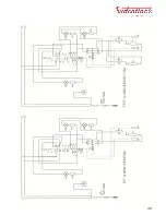
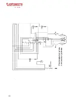
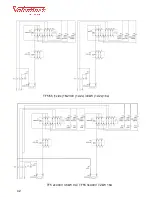
Wiring diagrams: see end of this manual


Pos


Component


T

F

7


T

F

7

7


T

F

7

T


T

F

7

7

T


T

F

1

0


T

F

1

3


M

a

x

i 5


T

F

5

5


T

F

5

5


Article 

code


Diagram 

code


Specifications


[2]


Neutral control lamp


1


2


1


2


1


1


1


2


2


6324


H1


230V


[3]


Orange control lamp


1


2


1


2


1


1


1


2


2


6325


H2


230V


[4]


Green control lamp


1


2


1


2


1


1


2


2


6326


H3


230 V


[1]


Thermostat


1


A5040

-

02


S1+S2


1P 16A 400V


[1]


Thermostat


1


2


1


2


1


2


2


A0040

-

01


S1+S2


3P 16A 400V


[1]


Thermostat


1


A0040

-

13


S1+S2


3P 16A 400V


[18]


Safety thermostat


1


A5040

-

03


S3


16A 400V


[18]


Safety thermostat


1


2


1


2


1


1


2


2


0705

-

04


S3


3P 16A 400V


[19]


Safety switch


2


4


2


4


2


2


4


4


6321


S5, S6


1P 16A 250V


[1]


Button


1


2


1


2


1


1


1


2


2


2694


[10]


Drain valve


1


2


1


2


1


1


2


2


5137


Heating element 


Heating element Maxi

-

5


1


A5030

-

01


R1,R2,R3


230V 3000W


Heating element  TF7 230V


1


2


A1030

-

02


R1,R2,R3


230V 3600W


Heating element TF 10 + TF13


3


3


A1030

-

01


R1,R2,R3


230V 2300W


Heating element  TF7 400V


1


2


A1030

-

03


R1,R2,R3


400V 3600W


Heating element  TF7T


2


4


A3030

-

01


R1,R2,R3


400V 2300W


Heating element  TF55 230V


2


A1030

-

04


R1,R2,R3


230V 3600W


Heating element  TF55 400V


2


A1030

-

05


R1,R2,R3


400V 3600W


Baskets


Basket TF7 and Maxi 5


1


2


1


2


1


A1080

-

02


220/235/108


Basket TF10


1


A3080

-

02


305/235/108


Basket TF13


1


A4080

-

02


440/235/108


2


2


A5580

-

02


155235/108


Basket TF55


Summary of Contents for TF55

Page 1: ...etriebsanleitung Original manual Valentine Fabrique SA 2018 Friteuses de table Manuel d utilisation p 2 Tisch Fritteusen Bedienungsanleitung p 11 Table fryers User manual p 20 MAXI 5 TF5 55 TF7 77 TF1...

Page 2: ...team and splashes of oil when cooking Never put anything other than food into the oil pan e g sealed containers etc oth erwise these may explode and splash out burning hot oil The oil level must never...

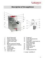
Page 3: ...Basket suspension bracket 7 Thermostat sensor on heating element 8 Oil level mark 9 Heating element 10 Drain valve 11 Drain valve lock 12 Discharge 13 Safety thermostat bulb 14 Push nipple 15 Red but...

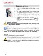
Page 4: ...ith oil set the switch 1 to 0 Never heat up without oil Safety switch Once the heating element is raised more than 5 mm the safety switch is activated and interrupts the current make sure that the hea...

Page 5: ...s deliv ered with the appliance Cooking table Temp Food being fried Minutes 190 o C Frozen chips 3 4 160 o C Prefrying raw chips 4 6 190 o C Frying blanched chips until golden 2 3 170 o C Breaded cutl...

Page 6: ...with a brush not made of metal Do not damage the bulbs of the thermostat 13 with sharp or pointed tools Remove the heating element box Do not immerse the housing in liquid Also clean the bottom of th...

Page 7: ...ing element and place it on the lid Until the thermostat bulb 13 attached to the heating element cooled down you cannot reset the safety thermostat Press down firmly on the red button 15 until you hea...

Page 8: ...5 6 2x 11 5 13 16 2x 16 Frequency Hz 50 60 Capacity in litres 7 7 7 10 13 2x 7 2x 7 4 2x5 2x5 Yield with frozen chips kg h 7 9 7 9 10 12 14 16 14 18 14 18 20 24 6 8 14 18 14 18 Yield with non frozen c...

Page 9: ...S2 3P 16A 400V 18 Safety thermostat 1 A5040 03 S3 16A 400V 18 Safety thermostat 1 2 1 2 1 1 2 2 0705 04 S3 3P 16A 400V 19 Safety switch 2 4 2 4 2 2 4 4 6321 S5 S6 1P 16A 250V 1 Button 1 2 1 2 1 1 1 2...

Page 10: ...ective 2014 30 UE RoHS Directive 2011 65 UE Food contact materials 1935 2004 CE WEEE Directive 2012 19 UE Standards IEC 60335 1 2013 ed 5 1 am2 2016 IEC 60335 2 37 2017 EN 60335 1 2012 A11 EN 60335 2...

Page 11: ...Sch mas lectriques Maxi TF Schalpl ne Maxi TF Wiring diagramm Maxi TF Esquemas electricos Maxi TF...

Page 12: ...39...

Page 13: ...40...

Page 14: ...41...

Page 15: ...42 TF5 2x400V 3 6kW 9A TF55 3x400V 7 2kW 16A TF5 55 1x 2x 1N230V 1x 2x 3 6kW 1x 2x 16A...

Page 16: ...original Originalbetriebsanleitung Original manual Valentine Fabrique SA 2018 Valentine Fabrique SA Z I Moulin du Choc E CH 1122 Romanel sur Morges T 41 21 637 37 40 F 41 21 637 37 41 info valentine c...

Reviews: