21
3
4
21
20
8
10
12
1
2
5
6
9
13
7
11
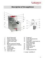
Description of the appliance
1.
Switch
-
thermostat
2.
White control lamp
3.
Orange control lamp
4.
Green control lamp
5.
Dial
6.
Basket suspension bracket
7.
Thermostat sensor on heating
element
8.
Oil level mark
9.
Heating element
10.
Drain valve*
11.
Drain valve lock*
12.
Discharge*
13.
Safety thermostat bulb
14.
Push nipple
15.
Red button = reset button for
safety thermostat
16.
Connecting cable
17.
Nameplate
18.
Safety thermostat
19.
Safety switch
20.
Tank
21.
Heating element box
(*) except model Maxi
-
5
Summary of Contents for TF55
Page 12: ...39...
Page 13: ...40...
Page 14: ...41...
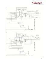
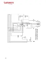
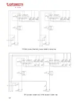
Page 15: ...42 TF5 2x400V 3 6kW 9A TF55 3x400V 7 2kW 16A TF5 55 1x 2x 1N230V 1x 2x 3 6kW 1x 2x 16A...


