Valcom V-A11012 Installation Manual Download Page 3

3

Valcom, Inc.
5614 Hollins Road
Roanoke, VA  24019
USA

P. 540-563-2000
F. 540-362-9800
www.valcom.com

Valcom, Inc.
5614 Hollins Road
Roanoke, VA  24019
USA

P. 540-563-2000
F. 540-362-9800
www.valcom.com

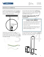
Important Safety Instructions
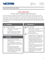
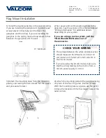
VERY IMPORTANT:

KNOW YOUR COMMUNICATION PROTOCOL

The Valcom Wired clock is designed to support the 2-Wire Digital Communication Protocol as well as 
3-wire (sync-wire) communication protocols. To run either system properly, the clock requires the correct 
wiring format. It is very important that you only follow the wiring instructions appropriate to your clock’s 
communication protocol. For example: if your system includes converter boxes which are only used for the 
2-wire system, then you should only follow the instructions that relate to the 2-wire digital communication  
protocol wiring. 

,

H

|

DANGER

SHOCK HAZARD

•  Keep the electricity to this device turned 

OFF until the clock installation  

is complete. 

•  Do not expose the clock movement to 

water, or install the clock in a location 

where it may be exposed to water.

WARNING

FIRE HAZARD

•  Always follow your national and regional 

electrical codes or ordinances. 

•  The AC power circuit for the clock must 

be attached to a circuit breaker that can 

be reset by the user.

PHYSICAL INJURY HAZARD

•  If you are standing on an object while 

installing your clock, make sure that the 

object can support your weight, and will 

not sway or move as you stand on it. 

•  Take precautions to avoid injury by 

potential safety hazards near the point 

of installation including (but not limited 

to) heavy machinery, sharp objects, hot 

surfaces, or exposed cables carrying an 

electric current. 

•  Follow all mounting instructions exactly 

as stated in this manual. Failure to do so 

may result in the device falling off the 

point of installation.

•  Packaging materials and mounting items 

include plastic bags and small pieces, 

which pose a suffocation hazard to 

young children.

NOTICE

•  Do not install the clock outdoors. 

Damage to the clock if placed outdoors 

voids the warranty.

•  Do not hang objects from the clock or 

clock mounting parts. The clocks are not 

designed to support the weight of other 

objects.

•  The clock face and housing may 

be cleaned with a damp cloth or 

disinfectant. Test other cleaning products 

on a small part of the clock housing 

before attempting to use on the rest of 

the clock. Avoid bleach and chemicals 

known to dissolve plastics.

!

!

Summary of Contents for V-A11012

Page 1: ...d Roanoke VA 24019 USA P 540 563 2000 F 540 362 9800 www valcom com Valcom Wired Analog Clocks Installation Manual V2 0 Current as of November 2016 V A2412 V A2412B and V A2416 V A2416B V A11012 V A11...

Page 2: ...Installation 9 15 Double Mount Installation 16 20 Wiring Information 2 Wire Digital Communication 21 3 Wire Synchronous Sync Wire Communication 24V 22 3 Wire Synchronous Sync Wire Communication 110VA...

Page 3: ...power circuit for the clock must be attached to a circuit breaker that can be reset by the user PHYSICAL INJURY HAZARD If you are standing on an object while installing your clock make sure that the o...

Page 4: ...P 540 563 2000 F 540 362 9800 www valcom com Identify Your Clock A label containing the part number of your clock is attached to the clock movement ORIGINAL CLOCKS V A2412 V A2416 V A11012 V A11016 B...

Page 5: ...32x1 2 screw M4 0 5x10 10x1 5 Self tapping screw Wall anchor Additional grounding wire with connector 1 2 2 1 1 1 PLEASE NOTE A user will also have to provide a Phillips head screwdriver a small slot...

Page 6: ...floor CHECK YOUR WIRING The voltage between the white and black wires should measure 105 126 volts AC in the 110 volt model or 21 5 26 5 21 5 26 5 volts DC in the 24 volt model If you are using the 24...

Page 7: ...ed 7 Remove the gearbox pin then if the case is made of metal attach the grounding wire to the grounding tab below and to the right of the clock movement 6 Insert the wall anchor into the hole then re...

Page 8: ...mounting bracket The screws should pass through the top and bottom holes on the clock followed by the top and bottom holes of the mounting bracket 9 Attach the clock to the mounting piece so that the...

Page 9: ...Wall anchor Additional grounding wire with connector 1 2 not used 2 not used 1 not used 1 not used 1 Description Valcom analog clock Mounting Bracket Quantity 1 1 not used Picture Flag Mount Installat...

Page 10: ...E A user will also have to provide a Phillips head screwdriver a small slot head screwdriver a drill with a 1 4 inch drill bit a pencil a double gang box Four wall anchors that can support 50 lbs and...

Page 11: ...um 4 Attach the mounting plate to the gang box using only two of the four long silver 6 32x1 screws With the mounting plate as a guide use the pencil to trace the locations of the four larger holes at...

Page 12: ...any wiring through the mounting plate and attach a grounding wire to the mounting plate using one of the larger centered holes and the 10 32x3 8 screw 6 Reattach the mounting plate this time using all...

Page 13: ...plate so that the lip is on the top of the base and the holes for the screws are on the bottom of the base Hang the base on the mounting plate attach the wires from the bottom of the pole to the wire...

Page 14: ...nal details depending on your system 2 Wire Digital 3 Wire Sync Yellow Black White Black White Yellow 27 24 26 23 To next clock Power Common Master Clock CLOCK 1 Gang Box Green Green Ground 13 Remove...

Page 15: ...otation that you wish it to be viewed You should hear a snapping noise as the four clips on the adapter secure the clock in place Insert the screws again to complete the installation 16 If you feel th...

Page 16: ...analog clock Mounting Bracket Quantity 2 2 not used Picture Included in Package Included in Double Mount Kit Included in Wiring Kit A PK 12 2A PLEASE NOTE A user will also have to provide a Phillips...

Page 17: ...communication wiring to the gang box See the sections of this manual labeled Wiring Information for additional details depending on your system If you are using a 2 wire system pull the YELLOW and GRE...

Page 18: ...ate and attach a grounding wire to the mounting plate using one of the larger centered holes and the 10 32x3 8 screw 6 Reattach the mounting plate this time using all four long silver 8 screws then in...

Page 19: ...ng the two black screws you set aside before 10 Attach the power connectors to the wires you threaded through the pole Consult the diagrams below for additional help or see the sections of this manual...

Page 20: ...uld hear a snapping noise as the four clips on the adapter secure the clock in place Insert the screws again to complete the installation 12 Attach a power connector to the ports on the bottom of each...

Page 21: ...A2412B or V A2416B Wiring Information 2 Wire Digital Communication Valcom Master Clock V D2425B or V D2440B V C6124P and the V CCU are ordered as a V VCU Data In 2 Wire Digital Output to Clocks 24 VDC...

Page 22: ...ice charge will cover minor repairs major repairs will be subject to additional charges for parts and labor This Limited Warranty is in lieu of and excludes all other warranties expressed or implied a...

Page 23: ...k Circuit 10 Amp Contact Rating or Black Power Green Ground White Neutral Yellow Reset 24VDC or Clock Circuit 1 Clock Circuit 2 27 26 25 24 23 22 27 26 25 24 23 22 or means one pair of ports or the ot...

Page 24: ...rcuit 10 Amp Contact Rating or Black Power Green Ground White Neutral Yellow Reset 110VAC or Clock Circuit 1 Clock Circuit 2 27 26 25 24 23 22 27 26 25 24 23 22 or means one pair of ports or the other...

Page 25: ...g mount clock then a standard double gang box is required Do I need to power up all the clocks at the same time No Clocks that are added to the system after power up will begin running and wait for co...

Page 26: ...ired Clock will automatically recognize the protocol being used as soon as it receives data Can I change protocols if the system is running Yes There are two ways of doing this 1 Do nothing Within thr...

Page 27: ...sive Test 2 Compare the time that the last signal was recieved to the parameters of your protocol If the amount of time since the last signal was recieved is more than the amount of time since the clo...

Page 28: ...Test 1 Protocol Verification Original Only The purpose of Diagnostic 1 is to tell the user which protocol the master clock is using to communicate with the secondary clock Diagnostic 1 may be enabled...

Page 29: ...c Test 1 Protocol Verification B Model Only The second hand will remain on this number for 3 minutes and then the clock will revert to displaying the accurate time If the LED is flashing red A compreh...

Page 30: ...ay how much time has passed since the clock last received a communication signal Diagnostic Test 2 Comprehensive Test Original Only The clock hands will remain on these numbers for three minutes and t...

Page 31: ...ours ago Clock received communication between 8 and 9 hours ago Clock received communication between 9 and 10 hours ago Clock received communication between 10 and 11 hours ago Clock received communic...

Page 32: ...nufacturer s default Diagnostic 3 may be enabled by holding down the diagnostic button for five seconds If the Valcom Wired clock is performing this diagnostic then a green LED on the back will flash...

Page 33: ...l of the clock hands are pointing to 12 the test was completed successfully At the end of Diagnostic three the clock hands will be set to 12 00 00 The clock will not resume normal operation until the...

Reviews: