Vaisala Indigo 500 Series User Manual Download Page 21

1. Open the 2 hex screws on the cover of the transmitter using a 4-mm hex key.

2. Open the transmitter cover.
3. Hold the transmitter level against the installation surface and use a pen to mark the places

of the mounting holes. The mounting holes are 157 mm (6.18 in) apart.

4. Drill 55 mm (2.17 in) deep holes and insert wall plugs.

5. Mount the transmitter to a wall using 2 screws and a crosshead screwdriver. Place nylon

washers under the screws to protect the surface of the transmitter.

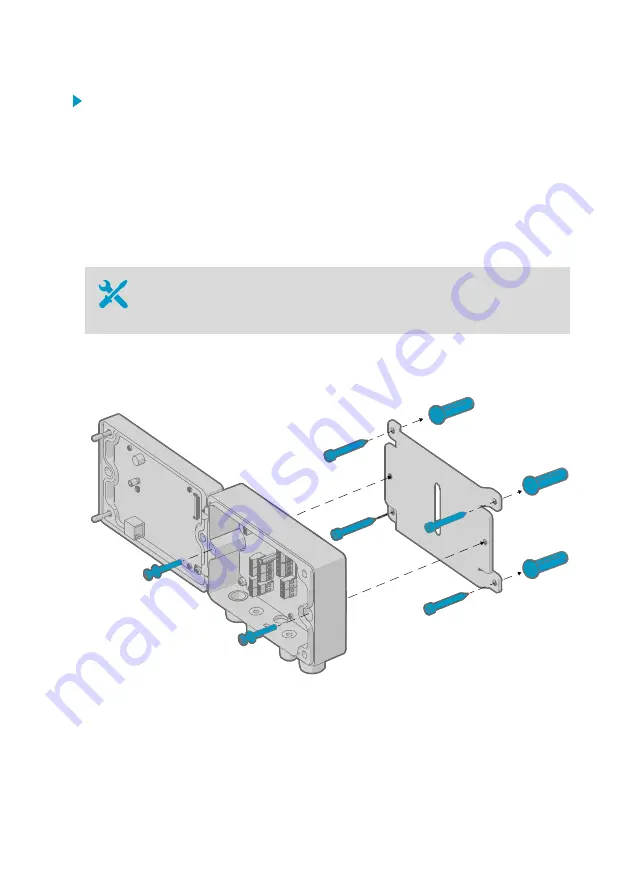
3.2.2 Wall mounting with adapter plate

• Hex keys (4 and 5 mm), provided
• Screws 14 mm (2 pcs), provided
• Washers (2 pcs), provided

• Wall screws (4 pcs)
• Wall plugs (4 pcs)

Using an adapter plate, you can install an Indigo 500 transmitter to replace a Vaisala 330
series transmitter in the exact same location.

Figure 4 Wall mounting with adapter plate

Chapter 3 – Installation

19

Summary of Contents for Indigo 500 Series

Page 1: ...M212287EN A User Guide Indigo 500 Series Transmitters Indigo 520...

Page 2: ...y given time and hereby disclaims any and all responsibilities related thereto This document does not create any legally binding obligations for Vaisala towards customers or end users All legally bind...

Page 3: ...5 compliance statement 15 2 9 2 Canada ICES 003 compliance statement 16 3 Installation 17 3 1 Opening and closing transmitter cover 17 3 2 Mounting 17 3 2 1 Standard wall mounting 18 3 2 2 Wall mounti...

Page 4: ...touchscreen 52 6 4 1 Relay configuration example 54 6 4 2 Relay wiring and relay activation mode 54 6 4 3 Relay hysteresis 55 6 5 Enabling Modbus TCP IP on touchscreen 55 7 Configuring transmitter us...

Page 5: ...Maintenance and calibration 77 Warranty 77 Technical support 77 Recycling 77 Table of contents 3...

Page 6: ...Measurements Home view on touchscreen 31 Figure 13 Configuration menu on touchscreen 32 Figure 14 Web interface and main views 33 Figure 15 Network settings on touchscreen 36 Figure 16 Date and time s...

Page 7: ...and probe 2 29 Table 8 Relay wiring Normally open NO 54 Table 9 Relay wiring Normally closed NC 54 Table 10 Unit IDs of transmitter and probes 61 Table 11 Transmitter options 70 Table 12 Operating en...

Page 8: ...Indigo 520 User Guide M212287EN A 6...

Page 9: ...ndigo 520 Quick Guide 1 3 Documentation conventions Warning alerts you to a serious hazard If you do not read and follow instructions carefully at this point there is a risk of injury or even death WA...

Page 10: ...demark of Schneider Automation Inc Microsoft Windows Internet Explorer and Edge are either registered trademarks or trademarks of Microsoft Corporation in the United States and or other countries All...

Page 11: ...HMP3 HMP4 HMP5 HMP7 HMP8 HMP9 and TMP1 Dew point probes DMP5 DMP6 DMP7 DMP8 CO2 probes GMP251 GMP252 Vaporized hydrogen peroxide probes HPP271 HPP272 MMP8 moisture in oil probe 2 2 Indigo 520 basic fe...

Page 12: ...al relay cable and power cable in the PELV and AC mains power supply options M20 1 5 lead through 7 Hex screws for opening the cover 2 3 1 Cable gland and conduit options The transmitter has 4 lead th...

Page 13: ...ies page 72 2 4 Touchscreen display You can configure the transmitter s capacitive touchscreen display to show numeric readings of 1 4 measurement parameters at the same time as well as graphs for 1 2...

Page 14: ...mple Firefox Chrome and Safari using the most recent version is recommended More information Web interface and main views page 33 Starting up transmitter using web interface page 38 Updating transmitt...

Page 15: ...transmitters that are powered with Power over Ethernet PoE More information Configuring relays on touchscreen page 52 Configuring relays in web interface page 58 2 7 Ethernet connection The transmitte...

Page 16: ...supply A readily accessible disconnect device must be incorporated in the fixed wiring WARNING Attach only Vaisala Indigo compatible probes to the transmitter CAUTION Do not modify the unit or use it...

Page 17: ...If you are unable to take either precaution touch a conductive part of the equipment chassis with your other hand before touching ESD sensitive components Hold component boards by the edges and avoid...

Page 18: ...ion between the equipment and receiver Connect the equipment into an outlet on a circuit different from that of the receiver Consult the dealer or an experienced radio TV technician for help Changes o...

Page 19: ...tter cover tighten the hex screws to 4 5 Nm 3 2 Mounting Choose the location of the transmitter so that the power outlet is accessible Besides the standard wall mounting the transmitter has the follow...

Page 20: ...vided Crosshead screwdriver Drill with 8 mm drill bit Screws 2 pcs provided Washers 2 pcs provided Wall plugs 2 pcs provided Figure 2 Standard wall mounting mm in 0 25 Figure 3 Transmitter mounting di...

Page 21: ...ugs 5 Mount the transmitter to a wall using 2 screws and a crosshead screwdriver Place nylon washers under the screws to protect the surface of the transmitter 3 2 2 Wall mounting with adapter plate H...

Page 22: ...ansmitter using a 4 mm hex key 3 Open the transmitter cover 4 Attach the transmitter to the adapter plate using 2 14 mm screws and a 5 mm hex key Place nylon washers under the screws to protect the su...

Page 23: ...e screws to protect the surface of the transmitter 4 Mount the transmitter on the DIN rail 3 2 4 Pole mounting Hex keys 4 mm and 5 mm provided Screws 14 mm 2 pcs provided Washers 2 pcs provided Instal...

Page 24: ...rtical pole mounting 1 Mounting nuts for fixing brackets M8 4 pcs 2 Note the position of the arrow when mounting This side must be face up when mounting Figure 8 Attaching transmitter to mounting plat...

Page 25: ...mitter cover Open ended spanners of sizes 17 mm 19 mm 22 mm and 24 mm Flat head screwdriver Cable glands as required by your application available from Vaisala Cables as required by your application p...

Page 26: ...ly licensed experts may connect the AC mains power connection to the power supply A readily accessible disconnect device must be incorporated in the fixed wiring WARNING Make sure that you prepare and...

Page 27: ...1 Strip 55 mm 2 17 in of the cable to expose the wires 2 Cut off 10 mm 0 39 in of the line and neutral wires Leave the grounding wire 55 mm 2 17 in long Make sure that the grounding wire is longer tha...

Page 28: ...ize 2 5 mm2 14 AWG Terminals in AC mains power supply version Type Push in spring connection Max wire size 1 5 mm2 16 AWG solid wires or ferrules recommended NO Relay 1 or 2 normally open NC Relay 1 o...

Page 29: ...e transmitter is powered off The 8P8C RJ45 Ethernet connector is located on the inside of the transmitter cover The supported standards are 10BASE T and 100BASE TX ANALOG OUTPUTS RELAY 1 RELAY 2 CH1 C...

Page 30: ...ter is powered off ANALOG OUTPUTS RELAY 1 RELAY 2 CH1 CH2 CH3 CH4 RS 485 PROBE 24 VOUT ANALOG INPUT NO COM NC NO COM NC 1 2 VS 1 2 For the M16 1 5 cable glands ordered together with the transmitter fr...

Page 31: ...ching probes Attach only Vaisala Indigo compatible probes to the transmitter CAUTION The IP classification of probes is valid only when the probes are attached to the probe connection cable CAUTION If...

Page 32: ...nection cable probe 2 3 Probe to be connected as probe 2 GMP252 example 4 Probe to be connected as probe 1 HMP7 example 5 Probe cable connector 5 pin M12 You can attach the probes to the wall using th...

Page 33: ...ettings and outputs 4 3 2 1 Figure 12 Measurements Home view on touchscreen 1 Slots for 1 4 configurable measurement parameters 2 Switch between the three Home views Measurements view 1 4 configurable...

Page 34: ...hat are currently active 4 Outputs Configure analog outputs relays and Modbus TCP IP 5 Transmitter Configure transmitter settings 6 Current IP address of the transmitter More information Starting up t...

Page 35: ...relays and Modbus TCP IP Administrator user level only 3 Transmitter Configure transmitter settings and update transmitter software Administrator user level only 4 Time 5 Display area for measurement...

Page 36: ...reen display 2 Power up the transmitter Powering up takes some minutes After the power up the Measurements Home view opens showing the 2 preferred measurement parameters from each connected probe 3 Se...

Page 37: ...ime Network 5 1 1 Configuring network connection on touchscreen Before you start find out from your local network administrator whether your transmitter uses dynamic or static network settings Dynamic...

Page 38: ...the configuration menu symbol at the upper right corner of the touchscreen 3 Select Transmitter Network 4 Make sure that Network off on is set on 5 Select the setting type Select DHCP if the transmit...

Page 39: ...ers Public computer server that translates the domain name of the transmitter into an IP address 7 Scroll to the end of the screen and select Apply to save your changes 5 1 2 Setting date and time on...

Page 40: ...d time select Manually b Select Time zone c In Date and time select Day Month Year and Time Then select Set d Select Date format and Time format The new date and time appears at the lower right corner...

Page 41: ...connect the Ethernet cable from the transmitter to the computer For a direct connection between the transmitter and your computer to work also make sure that the devices are in the same subnet and th...

Page 42: ...rs 5 2 2 Creating web interface users Hex key 4 mm for opening the transmitter cover When you connect to the web interface for the first time or when you start using the transmitter after a factory re...

Page 43: ...losure Use a 4 mm hex key to open the transmitter cover 3 Create a username and password for the Administrator user and select Next 4 Create a username and password for the Guest user optional and sel...

Page 44: ...interface 1 Type a username 2 Type a password 3 Select Log in The web interface opens in the Measurements Home view 5 2 4 Changing language in web interface 1 Log in to the web interface Indigo 520 Us...

Page 45: ...to use another language select it in User Preferences The language setting is web browser specific It is stored in the web browser s memory 5 2 5 Configuring network connection in web interface You n...

Page 46: ...lected Static IP fill in the rest of the fields with information provided by your local network administrator IP address The four part network ID of the transmitter Subnet mask Used together with the...

Page 47: ...Transmitter Date and time 1 Log in to the web interface as an administrator user 2 Select Transmitter Date and time 3 To set date and time automatically a In Set date and time select Automatically b...

Page 48: ...Time zone Date and Time 5 Select Apply More information Configuring web interface home view page 56 Configuring analog outputs in web interface page 57 Configuring relays in web interface page 58 Enab...

Page 49: ...ing touchscreen display 6 1 Accessing configuration menu 1 Select the configuration menu symbol at the upper right corner of the screen The configuration menu opens Chapter 6 Configuring transmitter u...

Page 50: ...rements view with slots for 1 4 measurement parameters 2 Graph view with graphs for 1 2 measurement parameters You can navigate between the views by using the left and right arrows at the bottom of th...

Page 51: ...ect the time scale for the graph To see the changes you made return to the Home views by selecting 6 3 Configuring analog outputs on touchscreen Analog outputs are not available in transmitters that a...

Page 52: ...Select the configuration menu symbol at the upper right corner of the touchscreen 2 Select Outputs Analog outputs 3 In the General tab define the settings that are common for all analog outputs a In...

Page 53: ...ically c In Scale low end and Scale high end define the lower and upper ends of the measurement scale for the chosen output parameter d Set the output channel on 6 Repeat step 4 step 5 for all the ana...

Page 54: ...he Output 1 tab Output off on Set output off to edit settings Parameter Probe 1 Relative humidity Scale low end 0 Scale high end 100 Output off on Set output on to activate settings 6 4 Configuring re...

Page 55: ...ls the relay c In Activation select whether the relay activates above or below the activation deactivation limit d In Limit define the limit which the measured parameter value must reach for the relay...

Page 56: ...mode The physical relay opens and closes the circuit depending both on the relay wiring and the relay activation mode Table 8 Relay wiring Normally open NO Relay activation mode Measurement above bel...

Page 57: ...the additional buffer value 1 3 2 Figure 24 Behavior of relay that activates above limit with hysteresis 1 Measurement goes above the relay activation limit solid line and the relay activates 2 Measur...

Page 58: ...surements view 1 Connect to the web interface 2 Log in to the web interface The web interface opens in the Measurements view 3 In the dropdown lists select the desired probe and measurement parameter...

Page 59: ...s Analog outputs 4 In the General tab define the settings that are common for all analog outputs a In Output mode select the current or voltage range for the outputs b In Error output define the outpu...

Page 60: ...ontrols the output channel d In Scale low end and Scale high end define the lower and upper ends of the measurement scale for the chosen output parameter e Set the output channel on f Select Apply 7 R...

Page 61: ...eb interface 1 Connect to the web interface 2 Log in to the web interface as an administrator user 3 Select Outputs Relays 4 Select the relay you want to configure Relay 1 or Relay 2 Chapter 7 Configu...

Page 62: ...ches off only when the measured value crosses the relay activation deactivation limit and the additional buffer value g Set the relay on h Select Apply 6 Repeat step 4 step 5 for all the relays you wa...

Page 63: ...TCP IP on touchscreen page 55 Enabling Modbus TCP IP in web interface page 60 8 2 Unit identification of transmitter and probes The transmitter and the connected probes are treated as separate Modbus...

Page 64: ...ed probe the transmitter responds with the exception code Gateway Path Unavailable For probe specific register information see the connected probe s Modbus documentation More information Modbus refere...

Page 65: ...long periods of time Do not immerse it in a chemical and wipe chemicals off the surfaces after cleaning 9 2 Replacing probes Attach only Vaisala Indigo compatible probes to the transmitter CAUTION If...

Page 66: ...new probe More information Attaching probes page 29 9 3 Updating transmitter software version You can update the transmitter software via the web interface You need Administrator user rights for this...

Page 67: ...ter restarts After the restart you can see the updated software version under System status If the transmitter s IP address is assigned via DHCP the transmitter may get a new IP address upon restartin...

Page 68: ...VATE WEB INTERFACE button while you power up the transmitter Keep pressing the button until the LED next to the button lights up ANALOG OUTPUTS RELAY 1 RELAY 2 CH1 CH2 CH3 CH4 RS 485 PROBE 24 VOUT ANA...

Page 69: ...o power up again This will take some minutes When the transmitter powers up it will continue to show measurements just like before the power outage To access the web interface again 1 Check the curren...

Page 70: ...ce login page problem above Check the solutions for the web interface login page problem above The Modbus off on setting may be off Make sure that Modbus off on is set on Menu path on touchscreen Menu...

Page 71: ...a status indicator check its color 2 If the indicator is off make sure that the probe is properly connected to the probe cable connector 3 If the indicator is red check the probe sensor If the sensor...

Page 72: ...ing altitude 3000 m 9843 ft Table 13 Inputs and outputs Property Specification Operating power Protective extra low voltage PELV version 1 15 35 VDC 24 VAC 20 max current 2 A Fuse size for power suppl...

Page 73: ...orted standards 10BASE T 100BASE TX Connector 8P8C RJ45 Supported protocols Modbus TCP IP port 502 HTTPS port 8443 1 The power supply option is selected when ordering the transmitter Table 14 Complian...

Page 74: ...e 215108 Probe connection cables Probe connection cable 1 m CBL210896 1MSP Probe connection cable 3 m CBL210896 3MSP Probe connection cable 5 m CBL210896 5MSP Probe connection cable 10 m CBL210896 10M...

Page 75: ...03hex Read Holding Registers Can be used only for reading probe registers for example measurement results using unit ID 241 or 242 See the connected probe s Modbus documentation for a probe specific...

Page 76: ...ts 2 02hex MajorMinorVersion 1 2 3 Software version of the device 3 03hex VendorUrl http www vaisala com 4 04hex ProductName INDIGO520 Transmitter 128 80hex SerialNumber 1 K0710040 1 Vaisala specific...

Page 77: ...h 7 06hex 07hex F1hex Unit identifier probe 1 F1hex Unit identifier probe 1 03hex Function Read Holding Registers 03hex Function Read Holding Registers 00hex Register address 04hex Number of data byte...

Page 78: ...used in actual communication based on the Modbus Reference in HMP4 User Guide Data format 2 16 bit Modbus registers interpreted as IEEE 754 binary32 floating point value least significant word first...

Page 79: ...Please observe that any such warranty may not be valid in case of damage due to normal wear and tear exceptional operating conditions negligent handling or installation or unauthorized modifications P...

Page 80: ......

Page 81: ......

Page 82: ...www vaisala com...

Reviews: