HMD70U/Y Operating Manual
M210277EN-C
2
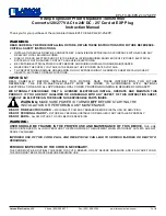
ELECTRICAL CONNECTIONS AND INSTALLATION OF THE CURRENT MODULE
INSTALLATION OF
THE CURRENT MODULE 18945HM
1. Take off the jumpers
2. Connect the module; note the
right direction!
3. Connect the power supply
OUTPUT SELECTIONS
0...1V
0...5V
0...10V
0...20mA
current
module
T
RH
RH
RH
RH
T
T
T
T
RH
TEST
CONNECTOR
1
1
1
1
2
3
4 5
current module 0...20 mA
U
U
U
U
RH OFFSET
T OFFSET
Us
RH
out
T
out
GND
V/mA
DC/AC
power supply
V/mA
RH GAIN
T GAIN
Figure 3: Electrical connections and installation of the current module
CONNECTION TO AN AC SUPPLY
HMD70U/Y transmitter
Controller
VAC
VAC
Us
GND
signal
RH/T
GND
Us
RH/T
signal
HMD70U/Y transmitter
Figure 4: The recommended AC connection
HMD70U/Y transmitter
HMD70U/Y transmitter
Controller
shared
common line
VAC
GND
GND
Us
Us
RH/T
RH/T
signal
signal
Figure 5: A common loop formed in an AC
connection
The HMD70U/Y transmitters can also be
connected to an AC supply without an
external rectifier. However, when more
than one transmitter is connected to one
AC transformer, a common loop is
formed and there is an increased risk of a
short-circuit. To avoid this, use a
separate floating supply for each
transmitter (see Figure 4). However, if
several transmitters have to share one
transformer, the phase (~) must always
be connected to U
s
connector in each
transmitter (see Figure 5).