background image

 *****INTERNAL*****30 R_D proof- 26.10.2022 / 09:15:46- VaillantGroup\DOC-agt\Brand\VIH_QW_190_6\ENG\OI-II_GB_0020291525

48

Installation and maintenance instructions 0020291525_04

D

Basic connection diagram for the energy supply company lockout, shutdown via
connection S21

 3~/400V

 1~/230V

BUS

S21

BUS

X106

L1

L1

L2 L3 N

L N

X300

X311

L N

X310

kWh

L1 L2 L3 N

L N

X200

BUS

X206

X210

L N

X211

kWh

2

2

N

L1
L2
L3

5

5

BUS

S21

BUS

X106

L1

L1

L2 L3 N

L N

X300

X311

L N

X310

L1 L2 L3 N

L N

X200

BUS

X206

X210

L N

X211

2

2

3

3

1

2

3

4

5

6

7

8

9

10

1

Meter/fuse box

2

Household electricity meter

3

Heat pump electricity meter

4

Ripple control receiver

5

Potential-free normally open contact, for actuating
S21, for the energy supply company lockout function

6

Disconnector (circuit breaker, fuse)

7

System control

8

Indoor unit, control PCB

9

Indoor unit, power supply PCB

10

Outdoor unit, PCB INSTALLER BOARD

Summary of Contents for uniTOWER plus

Page 1: ...en Operating instructions en Installation and maintenance instructions uniTOWER plus VIH QW 190 6 E GB 0020291525_04 26 10 2022 INTERNAL...

Page 2: ...2 en Operating instructions 3 en Installation and maintenance instructions 15...

Page 3: ...ety devices 8 4 Operation 8 4 1 Basic display 8 4 2 Operating concept 9 4 3 Menu display 9 4 4 Starting up the product 9 4 5 Setting the heating flow temperature 10 4 6 Setting the domestic hot water...

Page 4: ...that specified in this document shall be considered improper use Any direct commercial or industrial use is also deemed to be improper Caution Improper use of any kind is prohibited 1 2 General safet...

Page 5: ...ation in structions supplied with the product and that you have signed it to say that you have received a full and clear explana tion of its operation The installer is leg ally required to complete a...

Page 6: ...190 6 E GB 3 Product description 3 1 Heat pump system Design of a typical heat pump system with split technology 1 2 4 3 5 6 1 Heat pump outdoor unit 2 eBUS line 3 System control optional 4 Control f...

Page 7: ...e in the building circuit measured in the indoor unit The dashed lines show the permitted range Displayed statically Filling pressure in the permitted range Displayed flashing Filling pressure outside...

Page 8: ...cation Number on the Benchmark Checklist This product should be serviced regularly to optimise its safety efficiency and performance The service engineer should complete the relevant Service Record on...

Page 9: ...low 60 C without consulting the competent person first Depending on the source of the energy obtained from the environment target cylinder temperatures of up to 70 C can be reached with the compressor...

Page 10: ...ture Condition No system control connected Press in the basic display Use or to change the value and confirm this Condition System control connected Set the heating flow temperature on the system cont...

Page 11: ...heater Phase failure The product has an internal circuit breaker which switches off the heat pump in the event of short circuits or the failure of one product with 230 V power supply or several produc...

Page 12: ...lantGroup DOC agt Brand VIH_QW_190_6 ENG OI II_GB_0020291525 12 Operating instructions 0020291525_04 9 Guarantee and customer service 9 1 Customer service The contact details for our customer service...

Page 13: ...ctory setting Setting Min Max Basic display Right hand selection button Room temperature setpoint Current value Manual cooling demand Basic display Left hand selection button Domestic hot water cylind...

Page 14: ...mp tion of the heat pump without any external components connec ted as supplied Compressor modulation Current value Air inlet temperature Current value Immersion heater power Current value kW External...

Page 15: ...32 5 9 Connecting additional components 32 6 Electrical installation 32 6 1 Preparing the electrical installation 32 6 2 Requirements for the quality of the mains voltage 32 6 3 Electrical partition 3...

Page 16: ...d maintenance 43 11 5 Using check programmes 43 11 6 Checking the pre charge pressure of the expansion vessel 43 11 7 Cleaning the domestic hot water cylinder 44 12 Draining 44 12 1 Draining the produ...

Page 17: ...following work must only be carried out by competent persons who are sufficiently qualified to do so Set up Dismantling Installation Start up Inspection and maintenance Repair Decommissioning Proceed...

Page 18: ...bearing capacity to bear the operating weight of the product 1 2 8 Risk of material damage due to malfunctioning Not rectifying faults changing the safety devices and failing to carry out maintenance...

Page 19: ...rol fails the product guarantees limited frost protection for the heating circuit At negative outdoor temperatures there is an increased risk of the heating water freezing if a heat pump fault occurs...

Page 20: ...number may also be shown on the product s display Operating instructions 3 5 Information on the data plate The data plate keeps record of the country in which the product is to be installed Informati...

Page 21: ...o manage and promote the Scheme Benchmark is managed and promoted by the Heating and Hotwater Industry Council For more information visit www centralheating co uk 3 9 Energy balance control The energy...

Page 22: ...emperature 7 to 35 Permissible relative air humidity 40 to 75 Ensure that the required minimum clearances can be maintained Observe the permissible height difference between the outdoor unit and indoo...

Page 23: ...e access for maintenance and repair work When using the accessories observe the minimum clear ances installation clearances 4 7 Product dimensions for the transport 1985 4 8 Transporting the product D...

Page 24: ...during transport Remove the front casing before you use the carrying straps 2 To transport the unit safely use the two carrying straps on the two front feet of the product 3 If the carrying straps are...

Page 25: ...carry out the steps described above in reverse order 4 10 Removing the casing 4 10 1 Removing the front casing 2x1 2x1 1 5 x 5 5 1 5 x 5 5 D E C A A B 1 Remove the front flap on the control panel by t...

Page 26: ...out 4 10 2 Removing the side casing A B 2 1 C Remove the side casing as shown in the figure 4 11 Installing the casing 4 11 1 Installing the front casing 1 Install the upper part of the front casing a...

Page 27: ...that the front flap can move easily when it is opened from either side 4 11 2 Installing the side casing C B 2 1 A Install the side casing as shown in the figure 4 12 Moving the electronics box optio...

Page 28: ...are using metallic pipes to connect the pipe to the outdoor unit earth the pipes Heat insulate the pipes Only solder connectors if the connectors are not yet screwed to the service valves Carefully f...

Page 29: ...re at a domestic hot water draw off point 5 6 Hydraulic connection Caution Risk of damage caused by heat transfer when welding The heat that is transferred during welding may damage the cylinder and i...

Page 30: ...th the drinking water system 5 6 2 Installing a drain pipe 600 mm 300 mm D2 2 1 D1 1 Temperature and pres sure relief valve 2 Tundish Discharges at high level e g into metal hopper and metal downpipe...

Page 31: ...ge stack unless it can be demonstrated that the soil dis charge stack is capable of safety withstanding temperatures of the water discharged in which case it should contain a mechanical seal not incor...

Page 32: ...with a single tariff meter or a dual tariff meter 4 Connect the product via a fixed connection and a parti tion with a contact gap of at least 3 mm 5 Leave the cable cross section for the connection c...

Page 33: ...US A B 1 If required remove the left hand side casing 2 Guide the power supply cable 1 and other connection cables 24 V eBUS 2 along the left hand side casing in the product 2 1 1 3 Guide the power su...

Page 34: ...le power supply Energy supply company lockout provided shutdown via connection S21 Energy supply company lockout provided shutdown via partition Dual power supply 6 8 1 3 400V single power supply 1 2...

Page 35: ...issible total length of 125 m In this case a conductor cross section of 0 75 mm up to 50 m total length and a conductor cross section of 1 5 mm from 50 m In order to prevent faults in the eBUS signals...

Page 36: ...n X41 X24 6 4 3 2 1 5 7 8 9 12 11 10 13 14 15 16 1 2 3 4 5 6 DCF 0 0 FB AF RF 4 3 2 1 X35 Connect the connection cable for the external button using terminals 1 0 and 6 FB on the X41 edge con nector w...

Page 37: ...of suffi cient quality Before filling or topping up the installation check the quality of the heating water Checking the quality of the heating water Remove a little water from the heating circuit Ch...

Page 38: ...8 3 Filling and purging the heating installation 1 Flush the heating installation thoroughly prior to filling 2 Open all of the thermostatic valves on the heating in stallation and if required all oth...

Page 39: ...supply electric back up heater Immersion heater power limit electric back up heater Cooling technology Compressor current limit Relay multi function output Intermediate heat exchanger present Check pr...

Page 40: ...or in the heating circuit and a digital pressure display Select Menu Live Monitor to display the filling pressure in the building circuit 8 15 Activating cooling mode Go to the indoor unit s control p...

Page 41: ...ing and domestic hot water Since the heat pump installation regulates the building circuit pump at the nominal flow in automatic mode only set the parameters where required You can call up these param...

Page 42: ...via the Live Monitor menu 10 6 Using the function menu You can use the function menu to actuate and test individual components of the product during the fault diagnostics Section 10 7 10 7 Carrying o...

Page 43: ...manent fault and continues to run with restric ted comfort To determine which component is defective read the fault memory Section 10 3 Note If a fault message is present the product re mains in comfo...

Page 44: ...n der position Section 8 1 6 Open the automatic air vent red wheel 7 After five minutes open the air vent 3 If required close it again if water is escaping 8 Open the two stopcock in order to fully dr...

Page 45: ...re sensor Electric back up heater output 3 Building circuit flow 4 Building circuit return 5 Back up heater 6 Heating flow from the outdoor unit 7 Heating return to the outdoor unit 8 Prioritising div...

Page 46: ...wer supply PCB 2 For single power supply 230 V bridge between X311 and X310 for dual power supply Replace the bridge at X311 with the 230 V connection 3 Permanently installed protective conductor conn...

Page 47: ...Coding resistor 3 6 X24 Coding resistor 2 7 X41 Edge connector outdoor temperature sensor DCF system temperature sensor multi function input 8 X10⁶ S20 Limit thermostat 9 X10⁶ S21 ESCO contact 10 X106...

Page 48: ...L3 N L N X200 BUS X206 X210 L N X211 kWh 2 2 N L1 L2 L3 5 5 BUS S21 BUS X106 L1 L1 L2 L3 N L N X300 X311 L N X310 L1 L2 L3 N L N X200 BUS X206 X210 L N X211 2 2 3 3 1 2 3 4 5 6 7 8 9 10 1 Meter fuse b...

Page 49: ...US S21 BUS X106 L1 L1 L2 L3 N L N X300 X311 L N X310 kWh N L1 L2 L3 kWh L1 L2 L3 N L N X200 BUS X206 X210 L N X211 BUS S21 BUS X106 L1 L1 L2 L3 N L N X300 X311 L N X310 5 5 2 2 2 2 3 3 3 3 1 2 3 4 5 6...

Page 50: ...value Im heater power cons Current value kWh Im heater op hours Current value h Im heater switch ops Current value No switch ops Current value Installer level Test menu Check programmes P 04 Heating m...

Page 51: ...3 Temperature switch Compressor outlet Open Closed Open closed T 1 02 DHW prioritising diverter valve Heating Domestic hot water Heating domestic hot water Heating T 1 44 Cylinder temperature 40 90 0...

Page 52: ...ating mode only 1 7 Compressor hyster Cool 0 15 Applies for cooling mode only 1 5 Max rem feed head 200 900 mbar 10 900 DHW mode 0 ECO 2 Bal ance 0 ECO 1 Normal 2 Balance 0 Max anti cycl time 0 9 h 1...

Page 53: ...e installation assistant Yes back 1 See the overview of fault codes Fault lists are only available and can only be deleted if faults have occurred 2 This parameter does not appear if a system control...

Page 54: ...ating mode and domestic hot water mode S 203 Actuator test active The sensor and actuator test is currently operating S 212 Connection fault Con trol not recognised System control was previously detec...

Page 55: ...unit s power consumption is reduced the compressor speed is reduced The com pressor s operating current exceeds the limit value that is set under the configuration for 3 kW 5 kW 7 kW units 16 A for 1...

Page 56: ...check that the sensor is working correctly and if required replace the sensor M 203 Connection fault Disp not recog nised Display defective Display not connected Check the quality of the plug contact...

Page 57: ...sor Replace the wiring harness F 703 Sensor fault Low pressure The sensor is not connected or the sensor input has short circuited Checking the sensor e g using an installation aid and replacing it if...

Page 58: ...stop Use the sensor actuator test Check the compressor inlet sensor Check the refrigerant filling volume see technical data Check whether the 4 port diverter valve is in an intermediate position and...

Page 59: ...low temperature is lower than the return temperature in the building cir cuit The temperature sensor in the EEV environment circuit displays an incor rect temperature Check the 4 port diverter valve i...

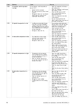
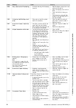
Page 60: ...rigera tion circuit if required F 824 Building circuit Brinepressure too low Note Can only occur in conjunction with an installed and activated intermedi ate heat exchanger set Fault refers to the out...

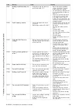
Page 61: ...and outdoor unit K 5 4 kW back up heater at 230 V and at 400 V Internal control of the output levels at 230 V and at 400 V Power consumption Set value 0 0 0 kW 1 0 7 kW 1 kW 2 1 2 kW 3 1 8 kW 2 kW 4...

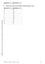
Page 62: ...680 105 588 110 510 N Characteristic values for the VR10 internal temperature sensors cylinder temper ature Temperature C Resistance ohms 40 88130 35 64710 30 47770 25 35440 20 26460 15 19900 10 15090...

Page 63: ...1525 0020291525_04 Installation and maintenance instructions 63 Temperature C Resistance ohms 150 51 O Characteristic values for the VRC DCF outdoor temperature sensor Temperature C Resistance ohms 25...

Page 64: ...e warranty rests with the end user consumer and they should be made aware it is ultimately their responsibility to register with the manufacturer within the allotted time period It is essential that t...

Page 65: ...G VWDEOH VXUIDFH FDSDEOH RI WDNLQJ LWV ZHLJKW Yes 7KH V VWHP KDV EHHQ XVKHG DQG FOHDQHG LQ DFFRUGDQFH ZLWK 6 DQG KHDW SXPS PDQXIDFWXUHU V LQVWUXFWLRQV Yes What system cleaner was used What inhibitor w...

Page 66: ...1R Comments Signature SERVICE 03 Date Engineer name Company name Telephone No 2SHUDWLYH 1R Comments Signature SERVICE 05 Date Engineer name Company name Telephone No 2SHUDWLYH 1R Comments Signature S...

Page 67: ...n Permissible water composition Technical data calculated without frost or corrosion protection Soften the heating water at water hardnesses from 3 0 mmol l 16 8 dH in accordance with Directive VDI203...

Page 68: ...a 5 50 bar Max water supply pressure to the pressure reduction valve 1 00 MPa 10 00 bar Volume of the internal diaphragm expansion vessel 8 l Volume of the external diaphragm expansion vessel 8 l Pre...

Page 69: ...80 min Power consumption during standby in accordance with DIN EN 16147 A7 with an outdoor unit up to 12 kW 39 W Coefficient of performance COPdhw in accordance with EN 16147 A7 XL profile with an out...

Page 70: ...lectricity 17 Energy supply company lockout 32 F Factory settings restoring 43 Fault codes 42 Fault memory 42 Fault symbol 43 Filling and purging 38 Filling pressure displaying 40 Front casing install...

Page 71: ......

Page 72: ...2859 Remscheid Tel 49 2191 18 0 Fax 49 2191 18 2810 info vaillant de www vaillant de These instructions or parts thereof are protected by copyright and may be reproduced or distributed only with the m...

Reviews: