*****INTERNAL*****30 R_D proof- 26.10.2022 / 09:15:46- VaillantGroup\DOC-agt\Brand\VIH_QW_190_6\ENG\OI-II_GB_0020291525
0020291525_04 Installation and maintenance instructions
19
2
Notes on the documentation
▶
Always observe all the operating and installation instruc-
tions included with the system components.
▶
Pass these instructions and all other applicable docu-
ments on to the end user.
These instructions apply only to:
Product
VIH QW 190/6 E GB
2.1
Further information
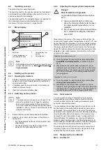
▶
Scan the displayed code using your smartphone in order
to view further information about the installation.
◁
You are guided to installation videos.
3
Product description
3.1
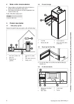
Heat pump system
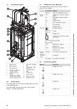
Design of a sample heat pump system with monoblock tech-
nology:
1
2
4
3
5
6
1
Heat pump, outdoor unit
2
eBUS line
3
System control
(optional)
4
Control for the indoor
unit
5
Heat pump, indoor unit
6
Heating circuit
3.2
Safety devices
3.2.1
Frost protection function
The frost protection function for the system is controlled us-
ing the product itself or using the optional system control. If
the system control fails, the product guarantees limited frost
protection for the heating circuit.
At negative outdoor temperatures, there is an increased risk
of the heating water freezing if a heat pump fault occurs, e.g.
due to a power cut or a defective compressor.
3.2.2
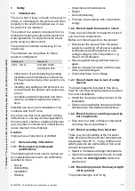
Low-water pressure protection
This function continuously monitors the heating water pres-
sure in order to prevent a possible loss of heating water. If
the water pressure falls below the minimum pressure, an
analogue pressure sensor switches the product off and, if
available, switches other modules to standby mode. If the
water pressure reaches the operating pressure, the pressure
sensor switches the product back on.
If the heating water pressure falls below
≤
0.1 MPa (1 bar),
a maintenance message appears below the display of the
minimum operating pressure.
–
Min. heating circuit pressure:
≥
0.05 MPa (
≥
0.50 bar)
–
Min. heating circuit operating pressure:
≥
0.07 MPa
(
≥
0.70 bar)
3.2.3
Safety cut-out (SCO) in the heating circuit
If the temperature in the heating circuit of the internal elec-
tric back-up heater exceeds the maximum temperature, the
safety cut-out shuts down the electric back-up heater as a
securing measure. After it is triggered, the safety cut-out
must be replaced.
–
Max. heating circuit temperature: 89
℃


