background image

Installation and maintenance instructions for uniSTOR 0020111105_00

17

5.3.2  Mounting the safety assembly

b

 Caution!

Risk of damage to the cylinder as a 
result of excess pressure!

Excess pressure can cause the cylinder to 
burst.


>

Make sure that there is no stop valve ins-
talled between the safety assembly 
and the cylinder. 

1

2

3

4

5

7

6

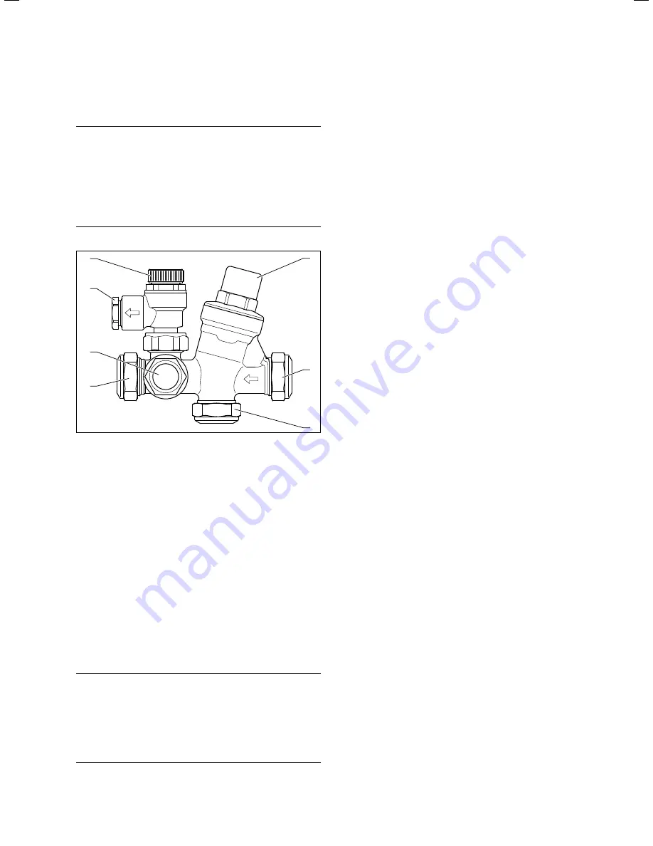
Fig. 5.4 Safety assembly

Key

1  Pressure reducing valve with line strainer
2  Cold water inlet 
3  Pressure-controlled cold water inlet
4 Cylinder 

connection

5  Hot water expansion vessel connection
6  15 mm expansion relief valve connection
7  Expansion relief valve


>

During the installation process, position the valves so 
that you are able to connect the 15 mm connection (

6

) of 

the expansion relief valve (

7

) with the tundish. Note the 

direction of flow, which is marked on the safety assembly 
with arrows.

i

  The safety assembly must be installed horizon-

tally with the expansion relief valve facing 
upwards (

¬ fig. 5.4

) in order to prevent the 

build-up of dirt.

b

 Caution!

Risk of damage to the cylinder as a 
result of excess pressure!

Excess pressure can cause the cylinder to 
burst.


>

Make sure that the expansion relief valve 
outlet is not covered or closed. 


>

Mount the discharge pipe of the expansion relief valve 
with a constant slope to the outside. The discharge pipe 
must finish at a safe and visible point where there is no 
danger of it freezing up and where it poses no risk of 
injury to persons.


>

Actuate the expansion relief valve regularly to prevent 
calcification. 


>

Connect the cylinder to the cylinder connection (

4

).


>

For the pipe from the main stop valve of the building to 
the cylinder, use copper piping with a diameter of at 
least 22 mm to ensure that the cylinder is as efficient as 
possible. This is particularly important for installations 
with a balanced cold water inlet (

3

).


>

Mount the safety assembly in the cold mains inlet on the 
cylinder. 


>

If necessary, establish the connection to the cold water 
inlet (

3

) with pressure compensation of the safety 

assembly. 


>

Depending on the fittings used and the type of the draw-
off points, it may be necessary to install a backflow pre-
venter in the pressure-controlled cold water inlet.

i

  If you mount the safety assembly above the cyl-

inder, you do not need to drain the cylinder in 
order to maintain the safety assembly. Make 
sure there is sufficient space for maintenance 
and connection of the discharge pipe of the 
expansion relief valve. 

When the discharge pipes are connected, the expansion 
relief valve may not be more than 600 mm away from 
the temperature and pressure relief valve (

¬ fig. 5.5

).

5.3.3  Mounting the expansion vessel

The Vaillant domestic hot water cylinder is delivered 
with an external expansion vessel.
Connect this expansion vessel to the installed safety 
assembly as follows:


>

Screw the expansion vessel directly to the safety assem-
bly via the provided connection (

5

) or 


>

Connect the expansion vessel with the safety assembly 
via a copper pipe or suitable hose line. Make sure the 
expansion vessel is supported sufficiently. 


>

Use the supplied wall bracket if you want to mount the 
expansion vessel to a wall.

i


In regions with high water pressure (4 bar or 
more), you can also connect the mixer tap for a 
bath or shower to the cold water inlet with pres-
sure compensation (3) of the safety assembly. 
This ensures that the hot and cold water supply 
to the mixer tap have the same pressure. You 
should install the cold water supply for all other 
connections using a T-piece before the safety 
assembly in the cold mains inlet to the cylinder.

Installation 5

Summary of Contents for uniSTOR

Page 1: ...Operating instructions For the operator GB IE Operating instructions uniSTOR domestic hot water cylinder ...

Page 2: ...instructions 5 3 Description of the unit 6 3 1 1 Safety devices 6 3 1 2 Hot water temperature regulation 6 3 1 3 Functional elements of cylinder 6 4 Operation 7 4 1 Setting the hot water temperature 7 4 2 Using the electric immersion heater 8 4 3 Switching off hot water production 8 4 4 Frost protection 8 4 5 Cleaning the cylinder 8 4 6 Temporarily taking the cylinder out of service 8 4 7 Energy s...

Page 3: ... danger Risk of death from electric shock b Symbol that denotes danger Risk of material damage Risk of damage to the environment i Symbol that denotes useful tips and information Symbol for a required action 1 4 Applicability of the instructions These operating instructions are valid exclusively for units with the following article numbers Unit type Cylinder volume Article number VIH GB 120 2 S 12...

Page 4: ...y Council who manage and promote the Scheme Visit www central heating co uk for more information 2 Safety instructions 2 1 Safety and warning information When operating the system observe the basic safety instructions and the warning notes which appear before each of the actions 2 1 1 Classification of warnings The warning notes are classified in accordance with the severity of the possible danger...

Page 5: ...on and servicing conditions Improper use of any kind is prohibited 2 3 Basic safety instructions Installation commissioning and maintenance Installation and adjustment as well as service mainte nance and repair must be carried out by a competent person approved at the time by the Health and Safety Executive and be in accordance with the relevant requirements of the Local Authority Building Regula ...

Page 6: ...r Primary heating circuit thermal cut out 3 1 2 Hot water temperature regulation You can set the hot water temperature and primary heating times on the controller One of the following controllers may be used depending on the design of your system Vaillant dual channel eBUS controller Cylinder thermostat in conjunction with a timer Observe the operating instructions for the installed con troller or...

Page 7: ...ylinder cold water connection which should have been fitted by your installer in an accessible position close to the cylin der 4 1 Setting the hot water temperature The hot water temperature is set to the required value by the competent person during cylinder commissioning If an external controller is installed for hot water tem perature control you can set the hot water temperature and primary he...

Page 8: ... production Switch off the gas fired wall hung boiler see operating instructions for the gas fired wall hung boiler to tem porarily switch off the heating and hot water system 4 4 Frost protection b Caution Risk of damage due to frost If the cylinder is placed out of operation for a relatively long period of time in an unheated room e g during a winter holi day the cylinder must be completely drai...

Page 9: ...which are already installed or can be retrofit ted in most circulation pumps Weather compensators often have ancillary functions for controlling circulation pump timings Consult your heating specialist company 4 8 Fault finding What do I do if Fault Remedy fluid is dripping from the system If possible collect the fluid in a bucket and inform a competent person the controller issues a message telli...

Page 10: ...lting from improper maintenance or repair Failure to arrange for the system to be maintained and repaired and improper maintenance and repair can impair the operational safety of the unit leading to personal injury and material damage Never attempt to perform maintenance work or repairs on the cylinder yourself Always employ a competent person 6 Recycling and disposal Both the Vaillant cylinder an...

Page 11: ...ompetent persons in accordance with all current and relevant safety building control and planning regulations and in full compliance with the manufacturer s instructions All unvented domestic hot water cylinders must be installed by a competent person to the prevailing build ing regulations at the time of installation G3 Terms and conditions apply to the warranty details of which can be found on t...

Page 12: ...6 116 115 Primary heat exchanger volume litres 2 94 2 94 3 56 3 56 3 56 3 56 Primary heat exchanger surface area m2 0 62 0 62 0 75 0 75 0 75 0 75 Dimensions Height mm 1001 1191 1371 1593 1843 2153 Height with hot water draw off mm 1033 1223 1403 1625 1875 2185 Topple measure mm 1138 1308 1473 1680 1918 2217 Diameter mm 554 5 Depth mm 633 Net weight kg 26 29 32 36 41 46 Weight full kg 145 177 8 209...

Page 13: ...i The heat up time is based on a flow rate of 1400 l h at 80ºC Temperature rise from 15ºC to 60ºC ...

Page 14: ......

Page 15: ......

Page 16: ...0020111106_00 GBIE 062011 Subject to change Manufacturer Supplier ...

Page 17: ...Installation and maintenance instructions For the competent person GB IE Installation and maintenance instructions uniSTOR VIH 2 S ...

Page 18: ...let 16 5 3 2 Mounting the safety assembly 17 5 3 3 Mounting the expansion vessel 17 5 3 4 Mounting the drain valve 18 5 3 5 Laying the pipes to the tundish 18 5 4 Installation of discharge pipe 18 5 4 1 Design of discharge pipe 18 5 4 2 High drain 19 5 5 Electrical installation 20 5 5 1 Electrical connection of control components 20 5 5 2 Connecting up the electric immersion heater 21 5 5 3 Option...

Page 19: ...Imminent danger to life Risk of severe personal injury Risk of minor personal injury e Symbol that denotes danger Risk of death from electric shock b Symbol that denotes danger Risk of material damage Risk of damage to the environment i Symbol that denotes useful tips and information Symbol for a required action 1 4 Applicability of the instructions These installation instructions are valid exclus...

Page 20: ...e the Scheme Visit www central heating co uk for more information 2 Safety instructions and regulations 2 1 Safety and warning information When conducting installation and maintenance work observe the general safety instructions and the warning notes which appear before each of the actions 2 1 1 Classification of warnings The warning notes are classified in accordance with the severity of the poss...

Page 21: ...umber The cylinder must be installed by a compe tent person approved at the time by the Health and Safety Executive to the prevailing standards installation book and building regulations at the time of installation 2 3 General safety instructions Installation commissioning up and maintenance Installation and adjustment as well as service mainte nance and repair must be carried out by a competent p...

Page 22: ... standards Pressure equipment directive 97 23 EC Directive of the European Parliament and Council of 29th May 1997 for the approximation of the laws on pressure equipment of the Member States EN 12897 2006 Water supply specification for indirectly heated unvented closed domestic hot water cylinders EN 806 1 Specifications for installations inside buildings conveying water for human consumption Par...

Page 23: ...nce with the relevant requirements of the Local Authority Building Regulations The Building Regulations Scotland The Building Regulations Northern Ireland and the relevant recommendations of the following British Standards BS 6700 Services supplying water for domestic use within buildings and their curtilages BS 6798 Specification for installation of gas fired boil ers not exceeding 60 kW input BS...

Page 24: ...e cylinder 2 4 3 7 6 1 B A 5 5 8 DHW M M M Fig 3 1 Hydraulics diagram for the connection of the unvented domestic hot water cylinder Key 1 Gas fired wall hung boiler 2 Cylinder 3 Two port motorised valve 230 V supplied with cylinder 4 Electric immersion heater 5 Two port motorised valve 230 V 3 Description of the unit ...

Page 25: ...Cylinder connection 8 Hot water expansion vessel 9 Tundish 10 Cylinder drain valve 11 Primary heater return 12 Cold water inlet 13 Primary heating circuit thermal cut out set to 80ºC to be con nected to the two port motorised valve in order to isolate the primary heat source if a fault occurs 14 Cylinder thermostat 25 C to 65 C 15 Primary heating circuit immersion sleeve NTC 16 Primary heater flow...

Page 26: ...r properties uniSTOR 260 or 310 litres 3 1 1 Safety devices The cylinder is delivered with all safety and control devices for the operation of the unvented domestic hot water supply system Temperature and pressure relief valve 90 C 7 bar Pressure reducing valve 3 5 bar with line strainer Expansion relief valve one way valve 6 0 bar Thermal cut out for electric immersion heater Primary heating circ...

Page 27: ...3 45 C 4 60 C 5 68 C Table 3 1 Setting the hot water temperature 3 1 4 Hot water temperature regulation You can control the hot water temperature using a Vaillant dual channel eBUS controller or a separate hot water controller a Danger Risk of burns and scalds Water at a temperature of more than 60ºC can escape from the water draw off point Install a hot water thermostat mixer in the hot water pip...

Page 28: ...116 116 116 115 Primary heat exchanger volume litres 2 94 2 94 3 56 3 56 3 56 3 56 Primary heat exchanger surface area m2 0 62 0 62 0 75 0 75 0 75 0 75 Dimensions Height mm 1001 1191 1371 1593 1843 2153 Height with hot water draw off mm 1033 1223 1403 1625 1875 2185 Topple measure mm 1138 1308 1473 1680 1918 2217 Diameter mm 554 5 Depth mm 633 Net weight kg 26 29 32 36 41 46 Weight full kg 145 177...

Page 29: ... valve connection 3 Secondary return 4 Primary heater flow Unit type a b c d e f g h i VIH GB 120 2 S 1033 1001 749 714 616 534 506 259 51 VIH GB 155 2 S 1223 1191 939 857 616 534 506 259 51 VIH GB 180 2 S 1403 1371 1119 992 616 534 506 259 51 VIH GB 210 2 S 1625 1593 1341 1158 616 534 506 259 51 VIH GB 260 2 S 1875 1843 1591 1346 616 534 506 259 51 VIH GB 310 2 S 2185 2153 1901 1578 616 534 506 2...

Page 30: ...able transportation aid sack truck or similar Transport the packaged cylinder to the installation site Only remove the cylinder from its packaging once it reaches the installation site 4 3 Installation site Position the domestic hot water cylinder as near as pos sible to the heater to prevent unnecessary heat loss Place the cylinder in a suitable location in the building paying attention to the fo...

Page 31: ... wrenches extensions etc b Caution Risk of damage from leaks Mechanical stress on supply lines can result in leaks and thus damage to the heat pump Avoid mechanical stress on supply lines 5 1 Installing pipes for the reheating circuit Make sure that the pipes in the reheating circuit between the gas fired wall hung boiler and cylinder are as short as possible Use copper piping with a minimum diame...

Page 32: ...ter for a second circulation line Connect a WRAS approved circulation pump 4 with a non return valve to the secondary return Connect the circulation line 3 to the hot water pipe 2 5 3 Installation of cold mains inlet 5 3 1 Pressure in cold mains inlet The efficiency of an unvented cylinder depends on the available pressure in the cold mains inlet and the flow rate To obtain optimum cylinder output...

Page 33: ...mm to ensure that the cylinder is as efficient as possible This is particularly important for installations with a balanced cold water inlet 3 Mount the safety assembly in the cold mains inlet on the cylinder If necessary establish the connection to the cold water inlet 3 with pressure compensation of the safety assembly Depending on the fittings used and the type of the draw off points it may be ...

Page 34: ...d pressure relief valve At least 300 mm Max 600 mm Fig 5 5 Typical drainage installation The discharge connections of the temperature and pres sure relief valve and the expansion relief valve must be connected to the supplied tundish via 15 mm copper pip ing The tundish should be mounted vertically as close to the cylinder as possible and not more than 600 mm from the connection of the temperature...

Page 35: ...vent children from coming into con tact with the waste water and provided that the system is not visible You must not install any valves or stop cocks in the discharge pipe Make sure that the discharge pipe from the tundish to the drain has a constant downward incline of at least 1 200 The discharge pipe from the pressure relief valve of the Vaillant gas fired wall hung boiler can be connected to ...

Page 36: ... P of the current IEE regulations and all other applicable regulations and directives You can use standard commercial cables for the wiring Minimum cross section of conductors 1 5 mm2 Maximum length of bus cables 300m 230 V supply lines and bus cables must be laid sepa rately above lengths of 10 m i The discharge pipes of the tundish drain valves and motorised valves etc must be laid at a dis tanc...

Page 37: ...1 Fig 5 9 Electrical connection of electric immersion heater Key 1 Protective earth terminal PE 2 Cable grip 3 Electric immersion heater 4 Neutral conductor terminal N 5 Outer conductor terminal L e Danger Risk of death from electric shock Without potential equalisation life threat ening voltage can reach the piping and water draw off points Earth the electric immersion heater b Caution Corrosion ...

Page 38: ...all hung boiler and control components used Gas fired wall hung boiler used eBUS compatible gas fired wall hung boiler such as the Vaillant ecoTEC or non eBUS compatible gas fired wall hung boiler from Vaillant or a third party manufacturer Wiring Wiring via the Vaillant VR 61 mixer module or Control Center VR 65 as a system solution which enables Vail lant dual channel eBUS controllers low voltag...

Page 39: ...Vaillant dual channel eBUS controller Vaillant dual channel eBUS controller with VR 65 S plan 1 fig 5 10 Vaillant ecoTEC eBUS compatible VR 65 Vaillant dual channel eBUS controller Vaillant dual channel eBUS controller with VR 65 Y plan 2 fig 5 11 Non eBUS compati ble boiler from a third party manufac turer Standard cabling box Programmable timer and room thermostat Timer S or Y plan 6 fig 5 12 Ta...

Page 40: ...ring diagrams Connection wiring diagram 1 S plan C 2 1 230 V grid VR 65 CH DHW BUS DHW NTC CYL 2 1 N PE on N PE L off on N PE on DO NOT USE M PE Blue Brown DHW M PE Blue Brown CH Cylinder thermostat and TCO 2 2 NTC BUS Vaillant ecoTEC BUS Vaillant dual channel eBUS controller 2 PE 3A N L Cylinder Fig 5 10 Connection wiring diagram 1 5 Installation ...

Page 41: ...ect the terminals 1 cylinder thermostat 3 fig 5 8 and C reheating circuit TCO 5 fig 5 8 to the terminal CYL of the VR 65 Mount the cover for the cylinder thermostat The electrical installation of the eBUS connection is described in the installation instructions for the Vaillant dual channel eBUS controller Install the eBUS connection from the gas fired wall hung boiler to the Control Center VR 65 ...

Page 42: ...plan C 2 VR 65 2 1 N PE on N PE L off on N PE on DO NOT USE M 2 2 NTC BUS Vaillant ecoTEC BUS Vaillant dual channel eBUS controller 2 PE 3A N L Cylinder 230 V grid CH DHW BUS DHW NTC CYL PE Blue Brown or white Grey Orange Cylinder thermostat and TCO 1 Fig 5 11 Connection wiring diagram 2 5 Installation ...

Page 43: ...tallation instructions for the Vaillant dual channel eBUS controller Install the eBUS connection from the gas fired wall hung boiler to the Control Center VR 65 Install the eBUS connection from the gas fired wall hung boiler to the Vaillant dual channel eBUS cont roller The electrical installation of the zone valves is described in the installation instructions for the VR 65 Connect the 3 way valv...

Page 44: ... on the use of cleaning agents for the system can be obtained from Sentinel Betz Dearborn Ltd Widnes Cheshire WA8 8UD Tel 0151 420 9595 or Fernox Alpha Fry Technologies Tandem House Marlow Way Croydon CR0 4XS Tel 0870 8700362 6 2 Water treatment b Caution Risk of material damage due to unsuita ble water Unsuitable water can lead to deposits and corrosion damage in the cylinder and in the hot water...

Page 45: ... supplementary water Once this triple system vol ume is exceeded the water will have to be treated exactly the same as in case of exceeding the limit values given in Table 6 1 softening desalination hardness stabilisation and desludging Table 6 1 Guidelines for the heating water Water hardness Heating water characteristics Unit Low salt Saline Electrical conductivity at 25ºC S cm 100 100 1500 Appe...

Page 46: ...ck it into this position Flush the entire primary central heating system including the reheating circuit with cold and hot water Flush fill and vent the central heating system in accordance with the installation instructions of the gas fired wall hung boiler Release the lever on the two port motorised valve by placing it in the AUTO position 1 2 3 4 5 1 2 3 Fig 6 2 Setting thermostats Remove the f...

Page 47: ...oning checklist located on the last few pages of these instructions 6 7 Handover to the operator You must brief the operator of the unit on the handling and function of the cylinder Provide the operator with all relevant instructions and unit documentation Go through the operating instructions with the operator and answer any questions Draw special attention to the safety instructions which the op...

Page 48: ...k the charge pressure of the expansion vessel re pressurise as necessary Annually Fill in the service section of the Benchmark cylinder commissioning checklist Annually Tab 7 1 Maintenance checklist 7 1 Checking the temperature and pressure relief valve and expansion relief valve Open each valve manually by turning the valve cap and check whether water is able to flow to the drain via the tundish ...

Page 49: ...ns a Danger Risk of death from electric shock Improperly executed work on the cylinder can result in a risk to life and limb Faults may only be eliminated by a com petent person approved at the time by the Health and Safety Executive b Caution Risk of damage due to overheating Not all electric immersion heaters have a thermal cut out Use only Vaillant Ltd electric immersion heaters with a thermal ...

Page 50: ...the two port valve Vent the reheating heat exchanger Check the thermal cut out and repair the fault Replace the cylinder thermostat Water flows out of the expansion relief valve only when heating up Dirt on the valve seat of the expansion relief valve Check the seat of the expansion relief valve and repair the fault Pressure reducing valve faulty Check whether the pressure behind the pressure redu...

Page 51: ...Prevent the power supply from being switched on again Ensure that any electrical work is carried out by a qualified competent person Switch the boiler off Drain the cylinder section 7 3 Dismantle the hydraulic connections Dismantle the temperature sensor Remove the wiring for the temperature sensor from the boiler or external controller 10 Recycling and disposal Both the cylinder and its transport...

Page 52: ...alled in accordance with The Water Regulations of England and Wales Water supply and fittings Regulations 1999 within England and Wales or Scotland The Water Byelaws Eire Compliance with IS standards and Local Council regulations Compliance with the Building regulations England and Wales Scotland Northern Ireland Eire Terms and conditions apply to the warranty details of which can be found on the ...

Page 53: ...Commissioning checklist and service record ...

Page 54: ...and pressure relief valve and expansion valve been WWHG and discharge tested Yes No The tundish and discharge pipework have been connected and terminated to Part G of the Building Regulations Yes Are all energy sources WWHG with a cut out device Yes No Has the expansion vessel or internal air space been checked Yes No THERMAL STORES ONLY What store temperature is achievable C What is the maximum h...

Page 55: ...omments Signature SERVICE 3 Date Engineer Name Company Name Telephone Number Comments Signature SERVICE 4 Date Engineer Name Company Name Telephone Number Comments Signature SERVICE 5 Date Engineer Name Company Name Telephone Number Comments Signature SERVICE 6 Date Engineer Name Company Name Telephone Number Comments Signature SERVICE 7 Date Engineer Name Company Name Telephone Number Comments Si...

Page 56: ...0020111105_00 GBIE 062011 Subject to change Manufacturer Supplier ...

Reviews: