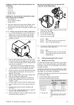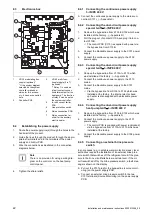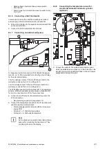
24
Installation and maintenance instructions 0020213394_05
8.5
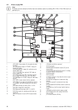
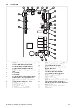
Power supply PCB
Note
The total current consumption of all connected external consumers (including X141, X143, X144, X145) must not
exceed 2.4 A.
X102
X110B
X120
F1
X110
X110A
X101
X145
X1A
X144
X105
X20A
LED
LED
X201
X200
X203
X202
X90
X140
X142
X104
X131
X750
X141
X143
X103
1
2
3
4
5
6
7
8
10
9
11
24
23
26
25
13
14
15
16
17
18
20
19
21
22
12
27
1
[X102] 400 V power supply for internal electric back-
up heater
2
[X110B] Optional bridge to X110 (230 V supply for
electronics system)
3
[X120] Optional 230 V supply for protection anode
(active tank anode)
4
[F1] F1 T 4A/250 V fuse (protects 230 V loads on
power supply PCB)
5
[X110] Power supply for 230 V electronics system
–
power supply PCB (TB) and control PCB (HMU)
6
[X110A] Bridge to X110 (230 V supply for electronics
system)
7
[X101] 400 V mains connection for compressor
8
[X103] Bridge for supplying internal back-up heaters
(if compressor and back-up heater have the same
tariff)
9
[X145] External back-up heater, 230 V, L N PE
10
[X1A] 230 V supply for control PCB
11
[X144] External 3-port valve, 230 V, L S N PE
12
[X105] Connection for compressor with in-rush cur-
rent limiter
13
[X20A] Connection for control PCB communication
line
14
LED safety switch for compressor
15
[X201] (not used)
16
[X200] Optional temperature sensors for ground
water module
17
[X203] Optional flow temperature sensor for heating
circuit with passive cooling module
18
[X202] (not used)
19
[X90] (not used)
20
[X140] Connection for 3-port diverter valve for pass-
ive cooling module
21
[X142] 3-port mixing valve for passive cooling
module
22
[X104] Connection for internal electric back-up
heater
23
[X131] Optional external brine pressure switch con-
nection
24
[X750] Safety cut-out for internal electric back-up
heater
25
LED safety switch for electric back-up heater
26
[X141] Signal output with cooling mode active,
230 V, L N PE
27
[X143] Well pump cut-off relay


