5 Set-up
18
Set-up instructions 0020200969_07
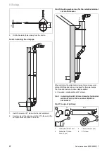
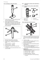
5.3.2.2 Determining the pipe length and the location
of the wall duct
87
Y + 24 - 28
1.
Determine the pipe length (
→
Installation instructions for
the boiler) and define the location of the wall duct.
2.
Measure the clearance Y from the external wall to the
installation surface for the boiler.
3.
Set the required pipe length: Y + 24 mm to 28 mm.
–
If you install the wall collar, add 12 mm to the total
pipe length.
–
If the terminal is below a roof overhang or a ho-
rizontal surface, you can pull the wall duct up to
500 mm out of the wall in order to guarantee that the
flue gases are extracted without any obstructions.
5.3.3
Installing the wall duct
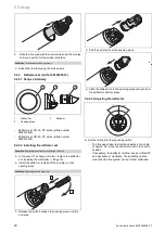
1.
Drill a hole.
–
Diameter: 110 mm
2.
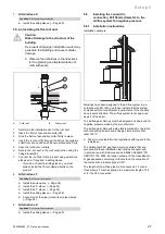
Push the air/flue pipe from outside and through the wall
and the terminals.
≥24
≤28
Ø3
1
3.
Pull the wall duct out to the required depth.
4.
Use the locking screws to secure the wall duct.
–
Use at least three of the six holes
(1)
that are avail-
able in the terminals to secure the flue pipe.
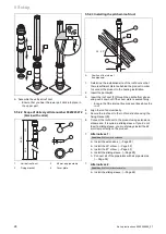
5.
Install the wall collar.
6.
Before you install the boiler, check that the wall duct is
safely secured in place.
7.
Seal the installation gap using a suitable material (e.g.
mortar).
8.
Install the boiler (
→
Installation instructions for the
boiler).
5.4
Installing terminal sets for 60/100 mm
diameter air/flue systems
5.4.1
Minimum clearances for the flue gas terminal
You must comply with the minimum clearances for the flue
gas terminal that are defined in BS 5440, unless the boiler's
manufacturer has given approval to use shorter minimum
clearances that are not considered to be safety-critical.
Vaillant has reduced the minimum clearances for the flue
gas terminal and specifies this in the installation instructions
for the boiler. These are minimum clearances that are to be
used for all types of installation, except for the installation of
the variable terminal set (VTK).
If a variable terminal set is connected to horizontal flue pipe-
work, terminal clearances are reduced for the air inlet. The
terminal clearances on the "new" flue outlet at the end of
VTK remain unchanged.
On the VTK, the minimum clearances for the air inlet A, B
and C (
→
Installation instructions for the boiler) to openings
(e.g. a window) are reduced to 150 mm. This means that
the terminal will be at the horizontal flue pipework when a
variable terminal set is connected to the air inlet and can
therefore be installed at a clearance of less than 300 mm
from a window opening or a ventilation tile.
5.4.2
Black terminal set 0020219537 (not for
0010035512)
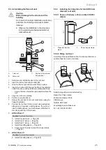
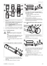
5.4.2.1 Scope of delivery
3
2
1
1
Wall collar
2
Terminal piece
3
End pipe


