Installation 5
0020134823_07 ecoTEC plus Installation and maintenance instructions
17
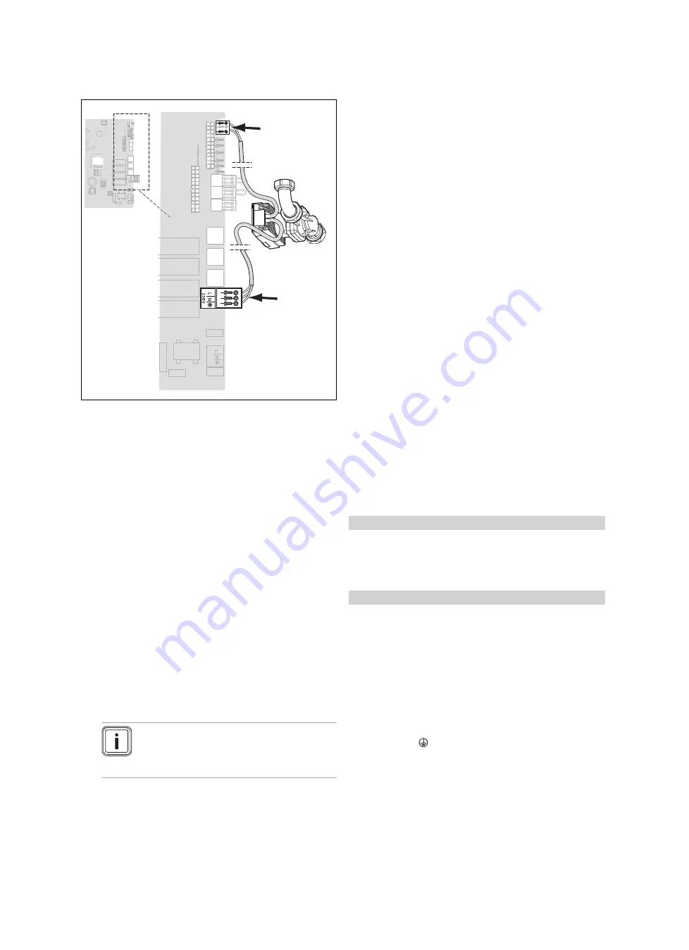
5.4.4
Connecting the pump group
X18
230 V
X22
1.
Open the electronics box. (
→
Page 16)
2.
Carry out the wiring. (
→
Page 16)
3.
Use the strain reliefs provided.
4.
Plug the ProE plug for the power supply cable into slot
X18.
5.
Plug the ProE plug for the control cable into slot X22.
6.
Close the electronics box. (
→
Page 16)
5.4.5
Installing the control
▶
Install the control if necessary.
5.4.6
Connecting controls to the electronics
1.
Open the electronics box. (
→
Page 16)
2.
Carry out the wiring. (
→
Page 16)
3.
If you connect a weather-compensated control or room
thermostat to the product via eBUS, bridge the input
24 V = RT (X100 or X106) if no bridge exists.
4.
If you use a low-voltage control (24 V), connect this
instead of the bridge 24 V = RT (X100 or X106).
5.
When connecting a limit thermostat (surface-mounted
thermostat) for underfloor heating, connect this instead
of the bridge (Burner off) at the ProE plug.
6.
Close the electronics box. (
→
Page 16)
Note
Due to the installed system separation, leave
the pump in the factory setting:
Comfort
D.018
5.4.7
Connecting additional components
You can use the multi-functional module to actuate two addi-
tional components.
The following components can be actuated:
–
Circulation pump
–
External pump
–
Cylinder charging pump
–
Extraction hood
–
External solenoid valve
–
External fault signal
–
Solar pump (not active)
–
eBUS remote control (not active)
–
Anti-legionella pump (not active)
–
Solar valve (not active).
5.4.7.1 Using the VR 40 (2 in 7 multi-functional
module)
1.
Install the components in accordance with the respect-
ive instructions.
2.
Select
D.027
(
→
Page 25) to actuate relay 1 on the
multi-functional module.
3.
Select
D.028
(
→
Page 25) to actuate relay 2 on the
multi-functional module.
5.4.7.2 Using the flue non-return flap
For cascade operation, you must provide a flue non-return
flap for each product. Either use only electrical flue non-re-
turn flaps or use only mechanical flue non-return flaps for all
products in a cascade.
The electrical flue non-return flap is actuated by the
VR 40
multi-functional module. The installation instructions for the
VR 40
describe how the flue non-return flap is activated. The
mechanical flue non-return flap has an integrated siphon,
which must be filled with water before starting up the unit.
You can omit the flue non-return flap if you can ensure that
the flue system is operated completely under negative pres-
sure.
Condition
: Operating with natural gas
▶
For smooth operation with natural gas and a flue non-re-
turn flap, use diagnostics code
D.050
(
→
Page 25) to in-
crease the offset for the minimum fan speed to the
fixed
value
of 1500 rpm.
Condition
: Operating with liquefied petroleum gas
▶
You must never raise the speed under
D.050
(
→
Page 25) any higher because a higher speed is
already being used when operating with liquid gas.
5.4.8
Actuating the circulation pump according to
requirements
1.
Connect the wiring in the same way as described
in "Connecting controllers to the electronic system
(
→
Page 17)".
2.
Connect the supply line for the external button using
terminals 1
(0) and 6 (functional drawing) on the X41
edge connector, which is supplied with the controller.
3.
Plug the edge connector into the PCB slot X41.
Summary of Contents for ecoTEC plus 1006 VU GB 1006/5-5
Page 59: ......


