background image

Instructions for Use, Installation and Servicing ecoMAX pro

15

7 Flue 

8 Installation preparation

1)

 In addition, the terminal should not be nearer than 150mm to an opening 

in the building fabric formed for the purpose of accommodating a built-in 
element such as a window.

2)

 Dimension B,C and D; These clearances may be reduced to  

25 mm without affecting the performance of the boiler. In order to ensure 
that the condensate plume does not affect adjacent surfaces the terminal 
should be extended as shown in Fig 7.4.

3)

 Dimension F; This clearance may be reduced to 25 mm without affecting 

the performance of the boiler. However, in order to ensure that the con-
densate plume does not affect adjacent surfaces a clearance of 300 mm is 
preferred. 

4)

 BS 5440-1 It is recommended that a fanned flue terminal should be posi-

tioned as follows: 
a) at least 2m from an opening in a building directly opposite, and 
b) so that the products of combustion are not directly directed to discharge 
across a boundary. For IE, recommendations are given in the current edition 
of IS 813.


TERMINAL POSITION  


mm

A

1)

  Directly below an opening, above an opening  


or horizontal to an opening i.e. air brick, opening  


window or other, etc 

300

B  Below gutters, soil pipes or drain pipes 

75

2)

C  Below eaves 

200

2)

D  Below balconies 

200

2)

E  From vertical drain pipes and soil pipes 

25

F  From internal or external corners 

300

3)

G  Above ground, roof or balcony 

300

H  From a surface facing a terminal 

600

4)

From a terminal facing a terminal 

1200

K  Vertically from a terminal on the same wall 

1500

L  Horizontally from a terminal on the same wall 

300

M  Distance from adjacent wall for vertical Flue 

500

balcony/eaves

flue extended to

clear any overhang

flue adequately

supported

gutter

7.3 Internal Flue Installation

The flue can be installed from inside the building when 
access to the outside wall face is not practicable.

7.4 Flue Options

There are various flue systems to choose from, as 
follows:
•  Vertical air/flue duct and terminal 

303 900

•  Air/flue duct extension (470 mm) 

303 902

•  Air/flue duct extension (970 mm) 

303 903

•  Air/flue duct extension (1970 mm) 

303 905

•  Telescopic air/flue duct extension 
(440 mm - 690 mm) 


303 906

• 87° elbow 


303 910

• Two 45° bends 


303 911

•  Standard horizontal air/flue duct 
with elbow and terminal (800 mm) 

303 930

Additional accessories are available.

8 Installation preparation

8.1 Unpacking of Boiler

Stand the boiler carton upright.
Cut and remove the securing straps and lift off the carton 
sleeve. Place aside the flue adaptor and connections 
pack until required.
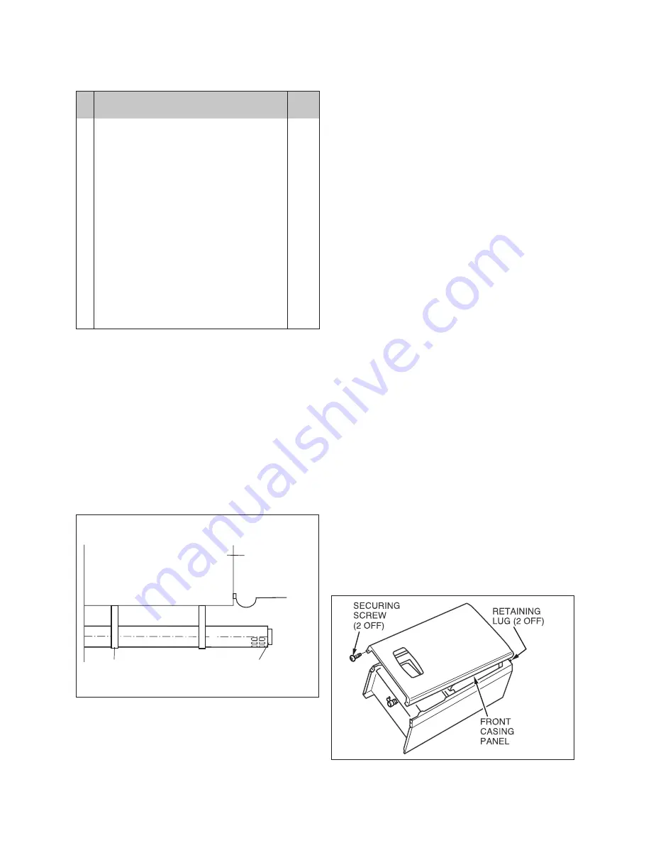
Carefully lay the boiler on its back, remove the two front 
casing panel securing screws and lift off the panel from 
two retaining lugs, see diagram 8.1.
Remove the two inner casing panel securing screws 
at the bottom front of the panel, then lift off the two 
retaining lugs, see diagram 8.2.

8.2 Using boiler template

Fix the paper template to the wall ensure that the
template is vertical.
The template shows
• The position of the fixing holes for the boiler mounting 

bracket (1).

• The position of the connections.
• The position of the flue exit hole.
Mark the position of the top hanging bracket fixing holes.
Drill 2 holes to accept the wallplugs/screws supplied for 
the hanging bracket.

NOTE: 

Use alternative fixing holes where necessary.

Fig 7.4

12677

Fig 8.1

12678

Summary of Contents for ecoMAX pro 18 E

Page 1: ...To be left with the user Instructions for Use Installation and Servicing ecoMAX pro Wall hung condensing boilers for traditional open vented systems GB 18 E 28 E ...

Page 2: ...ty Valve 12 5 9 2 Expansion Vessel 12 5 9 3 Pressure Gauge 12 5 9 4 Domestic Hot Water Cylinder 12 5 9 5 Water Makeup 12 5 9 6 Filling a Sealed Water System 12 5 10 Water Treatment 12 Page 6 Boiler Location and Ventilation 13 6 1 Boiler Location 13 6 2 Clearances 13 6 3 Timber Frame Buildings 13 6 4 Room Ventilation 13 6 5 Compartment Ventilation 13 7 Flue 14 7 1 Flue Position and Length 14 7 2 Fl...

Page 3: ...Spark Electrode 25 15 3 Burner 26 15 4 Combustion Chamber and Heat Exchanger 27 15 5 Condensate Drain 27 15 6 Inner Casing Panel Seal Check 27 16 Combustion analysis 28 17 Fault Finding 29 17 1 Status Mode 29 17 2 Fault Memory 31 17 3 Fault Codes 32 17 4 Fault Finding 33 18 Short Spare Parts 34 19 Boiler Specification 35 ...

Page 4: ...let 5 2 Guarantee card and envelope and log book 6 1 Template 7 1 Screws wallplugs 8 1 Gas service valve and compression couplers 9 1 Natural Gas to LPG conversion databadge oversticker Vaillant Ltd support the Benchmark initiative Within the information pack you will find a Benchmark Log Book It is very important that this is completed correctly at the time of installation commissioning and hando...

Page 5: ... body 0086 The CE mark on this appliance shows compliance with 1 Directive 90 396 EEC on the approximation of the laws of the Member States relating to appliances burning gaseous fuels 2 Directive 73 23 EEC on the harmonisation of the Laws of the Member States relating to electrical equipment designed for use within certain voltage limits 3 Directive 89 336 EEC on the approximation of the Laws of ...

Page 6: ...mme as long as the electricity and gas are left switched on This device operates the burner and system pump when the temperature inside the boiler falls to 3 C Any other exposed areas of the system should be protected by a separate frost thermostat If the mains electricity and gas are to be turned off for any long periods during severe weather it is recommended that the whole system including the ...

Page 7: ...y be used to switch off the boiler however it is preferable to leave the electrical supply on whenever possible to permit operation of the built in frost protection and daily pump exercise programme 2 17 Guarantee Our confidence in the quality of craftmanship and performance of our products is demonstrated by the Vaillant two year guarantee During the first year from installation the guarantee cov...

Page 8: ...Water Supply Water Fittings Regulations Water Bylaws The Health and Safety at Work Act Control of Substances Hazardous to Health The Electricity at Work Regulations the current IEE wiring regulations and any applicable local regulations Detailed recommendations are contained in the current issue of the following British Standards and Codes of Practice BS4814 BS5440 Part 1 and 2 BS5449 BS5546 BS670...

Page 9: ...Instructions for Use Installation and Servicing ecoMAX pro 9 Fig 4 1 12623 12624 Fig 4 2 4 General information ...

Page 10: ...A plastic drain pipe must be fitted to allow discharge of condensate to a drain Condensate should if possible be discharged into the internal household draining system If this is not practical discharge can be made externally into the household drainage system or a purpose designed soak away see Section 10 3 for more details 4 7 Heating System Controls It is recommended that a programmer and room ...

Page 11: ...ce please refer to 5 10 Water Treatment 5 6 Open Vented Water System The boiler must be supplied from an unrestricted water supply taken from a feed and expansion cistern situated at a maximum height of 27 metres 90ft above the boiler The cold feed must be 15mm minimum size The vent must rise continuously and be unrestricted It is important that the relative positions of the pump cold feed and ope...

Page 12: ... filling loop 5 9 Sealed water Systems The installation must comply with the appropriate requirements of the current issue of BS4814 BS5449 BS6759 BS6798 and BS7074 Part 1 and 2 For IE your attention is drawn to the current edition of IS 813 See Fig 5 4 for a suggested layout 5 9 1 Safety Valve A safety valve must be fitted to a sealed system It shall be preset non adjustable with a lift pressure ...

Page 13: ... or shower cannot touch it The boiler must be mounted on a flat wall which is sufficiently robust to take its total weight The boiler may be installed on a combustible wall subject to the requirements of the Local Authorities and Building Regulations The boiler is not suitable for fitting outdoors 6 2 Clearances The boiler should be positioned so that at least the minimum operational and servicing...

Page 14: ...vailable and can be used to achieve flue lengths up to 20 m A vertical flue system is also available Refer to flue system installation instructions for full details When extension pipes are used the flue system must be designed to have a continuous fall to the boiler of at least 3 to allow condensate to run out via the drain 7 2 Flue termination The following details refer to both flue systems a T...

Page 15: ...00 L Horizontally from a terminal on the same wall 300 M Distance from adjacent wall for vertical Flue 500 balcony eaves flue extended to clear any overhang flue adequately supported gutter 7 3 Internal Flue Installation The flue can be installed from inside the building when access to the outside wall face is not practicable 7 4 Flue Options There are various flue systems to choose from as follow...

Page 16: ... template to the side wall This dashed line is drawn at a 50 mm metre 3 rise from the boiler Where this line reaches the side wall a horizontal line should be marked The vertical centre line of the flue should then be marked at 176 mm from the back wall see Fig 8 3 To allow for the flue passing through the wall at this angle a 127 mm hole should be drilled irrespective of internal or external inst...

Page 17: ... the rear of the boiler see Fig 10 1 A 21 5 mm plastic overflow pipe should be connected to the spigot on the condense trap using the coupler The drain pipe should have a fall of a least 2 5 away from the boiler Condensate should if possible be discharged into the household internal drainage system If this is not practicable discharge can be allowed into the external household drains or a purpose ...

Page 18: ...e length of the extensions which should be taken into account when calculating the length that requires cutting For example Distance from outside wall to butt joint on the flue elbow Y 1500 mm Standard flue length 633 mm Extension pipe length 970 mm Length of extension pipe air duct 1500 633 867mm In this example the extension pipe would be cut to 867 mm this would be measured from the end of the ...

Page 19: ...h a small amount of sealant 11 3 Flue Assembly The flue assembly is a push fit design with securing collars Remove all burrs from cut pipes Fig 11 5 shows the components supplied in the standard kit and the flue adapter Having cut the air and flue ducts as described in sections 11 1 11 2 assemble the flue as follows the flue can be fitted externally or internally Fit the rubber sealing collar behi...

Page 20: ...hower b Both the plug and socket comply with the current issue of BS1363 Do not interrupt the mains supply with a time switch or programmer WARNING This appliance must be wired in accordance with these instructions Any fault arising from incorrect wiring cannot be put right under the terms of the Vaillant guarantee 12 1 Mains external controls and pump connections mains voltage ecoMAX pro boilers ...

Page 21: ...his will be done by the automatic burner sequence control 13 4 Initial Lighting The lighting procedure of the boiler is fully automated To prepare the boiler for initial lighting first ensure that all external controls are not calling for heat With the front casing panel and inner casing panel removed turn on the mains electrical supply Slide the On Off control down to the I position to turn on th...

Page 22: ...ve the handles from controls valve A and bypass valve B to prevent unauthorised adjustment 13 7 User Controls and Options The mains reset switch is used to restart the boiler after a fault condition has occurred i e ignition failure The user display see section 3 3 allows the user to set the desired central heating temperature 13 8 Temperature Display The boiler shows the operating temperature of ...

Page 23: ...Fig 14 4 fully clockwise Turn the throttle back anti clockwise 5 1 2 turns Ensure that the gas analyser is set to the correct fuel setting Propane To obtain conversion follow the procedure as below Connect a CO2 combustion analyser to the test point on the flue adaptor Turn on the gas service cock Turn on the electrical supply and slide the on off control down to the I position to turn on the boil...

Page 24: ...O2 with the B offset adjustment using a 2 mm allen key to 10 5 rotate clockwise to increase After checking the combustion press and hold the mode button for 10 seconds to return to the normal mode showing the current flow temperature Replace the cap on the sampling point and refit the outer front case Fit the LPG conversion label to the data badge Re commission boiler as described in the Installat...

Page 25: ...itted to the boiler When removing any water carrying components ensure that the water is kept away from all electrical components Always use new seals and O rings when replacing parts Always test for gas soundness and always carry out functional checks after any service work and after exchanging any gas carrying components Always check earth continuity polarity and resistance to earth with a multi...

Page 26: ...he electrical leads from the fan Remove the five combustion chamber front securing nuts see Fig 15 5 Gently remove the fan gas control valve and burner assembly from the combustion chamber complete with the gas pipe bracket and seal Clean the burner with a soft brush taking great care not to damage the front insulation DO NOT use wire or sharp instruments to clean the holes of the burner Inspect t...

Page 27: ...y remove the condense trap taking care not to spill any water which may be left in the unit As the unit is lifted remove the flexible pipe on the outlet Remove the cap at the base of the condense trap Remove any solids found Remove the float to clean it Flush water through the trap to remove any remaining solids Check for any debris in the outlet pipe of the condensate drain and clean as necessary...

Page 28: ...er interface in normal operating mode press and hold the mode button for 10 seconds until a flashing 0 appears Press the key and scroll through until 8 is shown on the left of the screen then press the mode button again Fig 16 3 12704 Fig 16 2 12703 Fig 16 1 12702 Press the key and scroll through until 96 installer mode is shown on the screen then press the mode button again Set the appliance fan ...

Page 29: ... 02 from cold m3 h Fault Finding Logical fault finding procedure These checks must be carried out before attempting to use the fault finding guide 1 Carry out electrical safety checks see section preliminary electrical checks 13 1 2 Check that the external electricity supply to the boiler is on and a supply of 230V is present at the boiler terminal strip 3 Check that the gas supply to the boiler i...

Page 30: ...t 10 Adaptive heating or night day switch No function adjustable 11 Night day setpoint Delta value No function adjustable 12 Central heating flow temperature C Read only 13 Central heating return temperature C Read only 14 Domestic hot water temp No function Read only 15 Tank temp No function Read only 16 DHW flow No function Read only 17 Extractor speed Extractor speed RPM x 100 Read only 18 Burn...

Page 31: ...5 fault memory screens are now available to be viewed memory 1 being the most recent Within each memory screen 5 additional screens provide further information to assist the installer engineer To cancel the fault memory mode proceed as follows Press and hold the mode button for 10 seconds until the screen returns to the user mode No Memory screen type Comments 1 Fault code Fault code 1 26 see page...

Page 32: ...at thermistor attached correctly to pipe F11 No reception by main board Connection fault between main PCB and interface Faulty interface Faulty main PCB processor Check fan F12 No reception by the local user interface As F 11 F13 Main board fault As F 11 F14 Central heating flow t 95 C System fault Possible external pump failure Check NTC on flow Check that pump is wired into appliance and not fro...

Page 33: ...Instructions for Use Installation and Servicing ecoMAX pro 33 17 Fault finding wiring diagram Fig 17 3 17 4 Fault Finding 12452 ...

Page 34: ...ption 1 190260 Fan assembly 2 090750 Spark electrode 3 091258 Igniter unit 4 053574 Gas control valve 5 101771 Heating flow return NTC 2 6 101191 Overheat stat 7 130837 Main PCB 8 256271 Mains Reset Switch 9 130839 Main user display interface 10 050469 Burner 18 E 10 050470 Burner 28 E 11 130838 230V interface PCB ...

Page 35: ...bar Gas supply G20 Gross CV s t 37 8 37 8 MJ m3 Maximum gas rate 2 00 3 02 M3 h Minimum gas rate 0 53 0 56 M3 h Burner CO2 Case on 9 0 0 2 9 0 0 2 Gas connection 15 mm Compression 15 mm Compression Water connections 22 mm Compression 22 mm Compression Condensate drain internal diameter min 19 19 mm Internal fuse ratings Fan supply PCB 3 15 AT Fan supply PCB 3 15 AT A Main PCB 125 mAT Main PCB 125 ...

Page 36: ...83 49 39 GB_02 2000225283A 11 04 11 2004 Subject to alteration ...

Reviews: