9 Inspection and maintenance
22
Installation and maintenance instructions ecoCRAFT exclusive 0020149561_01
8.
Explain to the operator how to check the required sys-
tem pressure and the measures for filling and purging
the heating installation, where required.
9.
Instruct the operator that, when filling the heating in-
stallation, the local water quality must be taken into ac-
count.
10. Inform the operator of the correct (efficient) settings
for temperatures, controllers, and thermostatic radiator
valves.
9
Inspection and maintenance
▶
Disconnect the product from the power mains.
Note
If inspection and maintenance work is neces-
sary when the main switch is switched on, this
is indicated in the description of the mainten-
ance work.
▶
Close the gas isolator valve.
▶
Remove the front casing. (
→
Page 10)
▶
Carry out all inspection and maintenance work in the
order shown in the table "Overview of inspection and
maintenance work".
Inspection and maintenance work
–
Overview
(
→
Page 34)
9.1
Observing inspection and maintenance
intervals
Proper regular inspections and maintenance (once a year)
combined with the exclusive use of genuine spare parts are
decisive factors in ensuring smooth operation and long work-
ing life for the product.
We recommend taking out an inspection and maintenance
contract.
Inspection
The inspection is intended to determine the actual condition
of the product and compare it with the target condition. This
is done by measuring, checking and observing.
Maintenance
Maintenance is required in order to eliminate any deviations
of the actual condition from the target condition. This is nor-
mally done by cleaning, setting and, if necessary, replacing
individual components that are subject to wear.
9.2
Procuring spare parts
The original components of the product were also certified
by the manufacturer as part of the declaration of conformity.
If you use other, non-certified or unauthorised parts during
maintenance or repair work, this may void the conformity of
the product and it will therefore no longer comply with the
applicable standards.
We strongly recommend that you use original spare parts
from the manufacturer as this guarantees fault-free and safe
operation of the product. To receive information about the
available original spare parts, contact the contact address
provided on the reverse of these instructions.
▶
If you require spare parts for maintenance or repair
work, use only the spare parts that are permitted for the
product.
9.3
Checking the CO/CO
₂
ratio
Note
Checking/adjustment of the CO/CO
₂
Ratio is re-
quired in the following instances:
- replacement of gas valve.
- or if an incorrect combustion is suspected
- during annual maintenance
1.
Make sure that there is an opening for the CO/CO
₂
measurement in the flue pipe. Connect a suitable flue
gas analyser to this opening to establish the combus-
tion performance of the boiler.
Note
The maximum draught should not exceed 20
Pa, as otherwise the results of the CO/CO
₂
measurement in minimum load will be in-
valid. If necessary you can remove the cover
of the inspection opening in the external ex-
haust gas ducting during the measurement.
Then replace it after the measurement.
2.
Remove the front casing.
3.
Start the testing program
P.1
for full mode (
→
Page 15).
–
Wait at least 5 minutes until the boiler reaches its
operating temperature.
4.
Measure the CO/CO
₂
Ratio at the flue pipe. Compare
the measured value with the corresponding value:
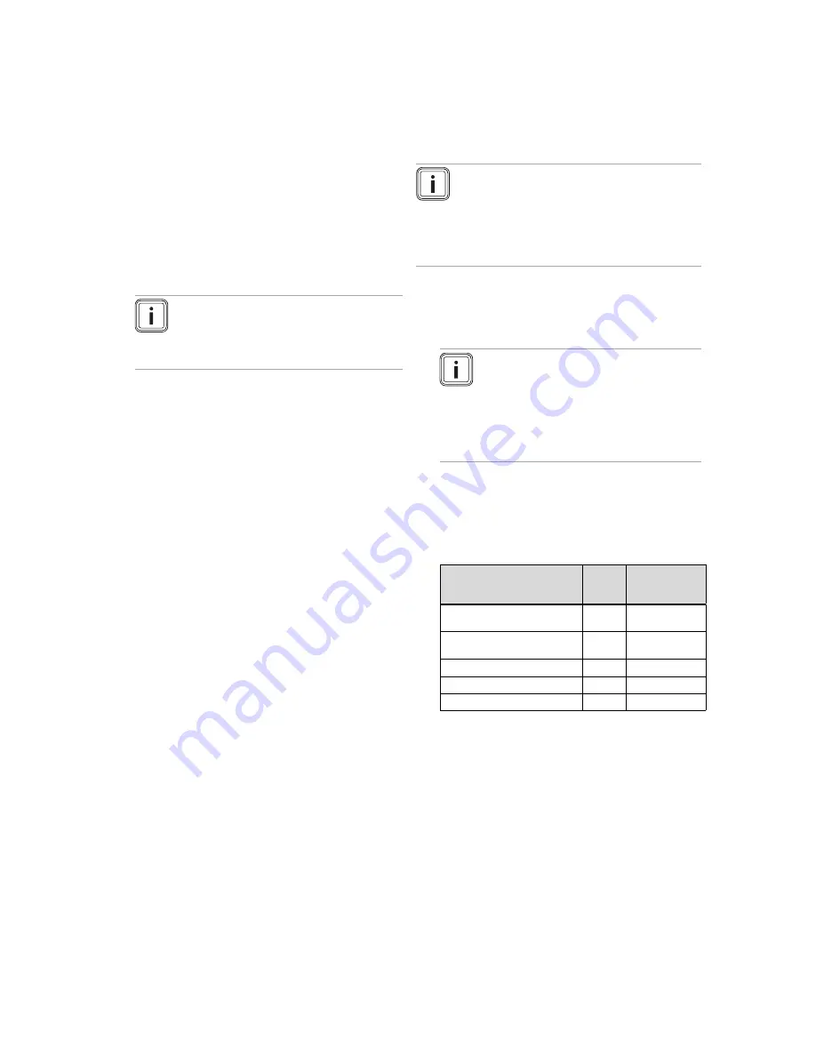
Settings for
VKK GB 806/3-E R1 - VKK
GB 2806/3-E R1
Unit
Natural gas (H)
Tolerance
CO
₂
after 5 minutes full load
mode (P.1)
Vol.
–
%
9.3
±
0.2
CO
₂
after 5 minutes minimum
load mode (P.2)
Vol.
–
%
9.0
±
0.2
Set for Wobbe index W
s
kWh/m
³
15.0
CO value with full load
ppm
< 200
CO/CO
₂
< 0.0023
5.
Start the testing program
P.2
for minimum load.
–
Wait at least 5 minutes until the boiler reaches its
operating temperature.
6.
Measure the CO/O
₂
Ratio at the flue pipe. Compare the
measured value with the corresponding value.
7.
If all these points are as required, leave the test mode.
8.
If one of the flue gas values is greater than the accept-
able values then proceed as described in the following.


