background image


9

5. TROUBLE SHOOTING 

5.1  GENERAL CHECKS (FIGURES 6 THRU 10). 

If the reason for the trouble is unknown, it is necessary to examine the printer to be sure it functions 
properly. 
Observe function of the no back pawl by turning the crank in a counter clockwise direction. The no 
back pawl should limit the rotation to 20 degrees. 
Turn the crank in a clockwise direction. The one-turn stop pawl should stop the crank after one 
complete turn. 
Turn crank until tray is in rear position and seal pin is up. 
While turning the crank, observe the following during the print-in cycle: 
a.  tray moves forward to print-in position, seal pin pierces ticket and wheels reset to zero. 
b.  print action occurs before stop. 
c.  simulate delivery by turning drive gear While delivery is being made sales number wheel 
advances one digit. 
 
Observe the following during the print-out cycle. 
a.  tray moves to rear printer. 
b.  print-out occurs showing the quantity delivered. 
c.  seal pin releases ticket before stop is reached. 
 
Check print wheel end play for 0,5 mm to 0,65 mm. 
Turn the printer so the printing arm faces you. Check the springs to see that they are properly 
anchored. 
Check roller on the printing arm for proper alignment on cam. 
 
Examine stop pawl for proper assembly. 
Turn the printer so the back faces you. Be sure the ticket stop screw is secure. 
Check the tray support rods to be certain they are free and secured in place by four clips. 
Turn the printer so the crank faces you. Be sure the springs are properly anchored. 
Examine the E-ring retaining and pins to be certain that they are properly seated and thight. 
Examine the three reset gears for damage or wear. Replace as required. 


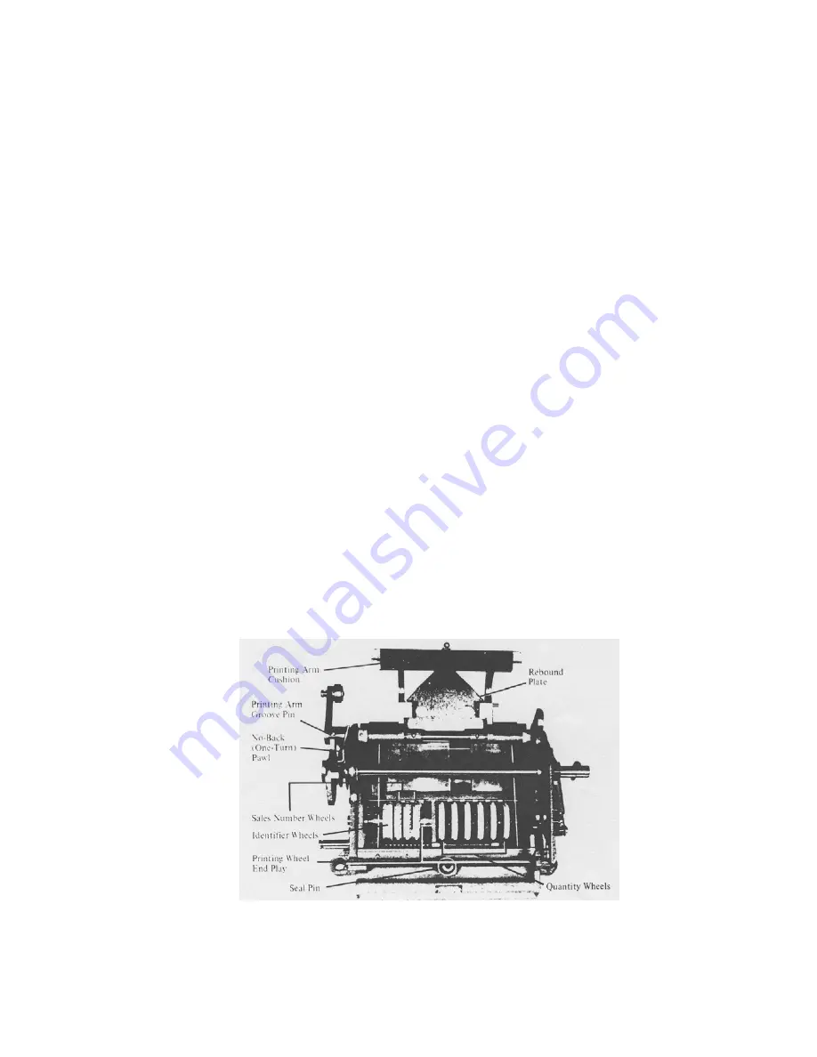
Fig. 6: Parts Identification 


Summary of Contents for 247

Page 1: ...Technical Manual Instructions for installation operation and maintenance 247 TICKET PRINTER For MidFlow and HiFlow series J Vane meters Publication nr TIB 247 GB 0711 Supersedes TIB 247 GB 1201...

Page 2: ...RAL 7 4 2 CLEANING 7 4 3 RECOMMENDED LUBRICATION 7 4 4 LUBRICATION POINTS 7 5 TROUBLE SHOOTING 9 5 1 GENERAL CHECKS Figures 6 thru 10 9 5 2 TROUBLE SHOOTING 11 5 3 TICKET POSITION ADJUSTMENT 12 5 4 SA...

Page 3: ...the operator and for your maintenance department To ensure safe and correct installation and operation study this manual carefully before starting operations For any additional information contact VA...

Page 4: ...because it begins to count at zero and returns to zero when reset The printer total is the amount of delivery 2 1 1 Drive The shaft figure 2 on the bottom of the printer is driven by a bevel gear from...

Page 5: ...nternal stop a As the printing crank is turned the reset drive gear figure 3 makes one complete clockwise revolution until a positive stop is reached As the ticket tray moves into position the seal pi...

Page 6: ...a counter clockwise direction The internal bevel gear on the shaft drives the clutch assembly associated pinions and the gear assembly of the right hand wheel 2 2 2 Printing In printing operation a ti...

Page 7: ...om the register 3 2 INSTALLATION After maintenance and repairs install the printer onto the meter as follows a Turn the printer crank until the tray is in outward position and seal pin down Remove pri...

Page 8: ...nd lubricate unit c If printing wheels are extremely dirty a small brush may be used to scrub the figures CAUTION DO NOT USE A WIRE BRUSH 4 3 RECOMMENDED LUBRICATION OIL Anderol L 401 D or equivalent...

Page 9: ...8 Fig 4 Lubrication points Fig 5 Lubrication points...

Page 10: ...delivery is being made sales number wheel advances one digit Observe the following during the print out cycle a tray moves to rear printer b print out occurs showing the quantity delivered c seal pin...

Page 11: ...10 Fig 7 Parts Identification Fig 8 Parts Identification Fig 9 Ticket Tray Actuating Pin Fig 10 Sales Advance Mechanism...

Page 12: ...e Check reset gears and time as required See Section 6 Wheels fail to reset to zero Spring missing from wheel pawl or broken pawl Replace defective wheel See Section 6 Input shaft binds when turned by...

Page 13: ...he ticket properly then replace shield and screws Fig 11 Ticket Position Guides and Stop Screws 5 4 SALE NUMBER ADVANCING MECHANISM INSPECTION Sale number advancing mechanism figure 12 is tripped when...

Page 14: ...shed by turning the adjusting set screw figure 13 Turning screw clockwise the inching occurs at a higher number and counter clockwise at lower inching numbers With reference to the printing only inchi...

Page 15: ...shaft Pull shaft out from right side until flush with frame Leave gears engaged Remove all tray rod clips and tray support rods Lift tray up while tilting left side up Fig 14 Ticket Tray Parts Identif...

Page 16: ...allow tray stud to pass through opening in frame right side Be sure that tray stud enters internal groove of actuating cam Install tray support rods Double groove must be at right in front position a...

Page 17: ...Install crank shaft as outlined in 6 4 Hold tray in rear position and install reset gear on stud To check internal cam engagement will tray stud rotate reset gear two revolutions noting tray movement...

Page 18: ...17...

Page 19: ...ove Pin 18 W0600 020 Rebound plate 19 J054 0080 Spring 20 W5202 094 Spring 21 22 W7778 847 Print Arm Lever Pin 23 W6104 060 Washer 24 W7779 413 Pawl 25 W0600 079 Spring 26 W1601 081 Collar 27 W0600 01...

Page 20: ...W0601 034 Spring clutch 62 W0602 008 Transfer Disc 63 W5201 061 Spring clutch 64 W0602 007 Detent 65 W2671 028 Driver 66 W3005 051 Bevel 67 W5201 062 Spring clutch 68 W3071 435 Gear 69 W6104 031 Washe...

Page 21: ...06 W0601 032 Detent Spring 107 W0601 031 Detent 108 W6105 010 Lockwasher 109 W4102 011 Nut 110 J054 0087 Grub Screw 111 J054 0088 Bevel 113 W6104 026 Washer 114 W6104 031 Washer 115 W2371 040 Serial P...

Page 22: ...nt this remaining at the discretion of the contractor Subarticle 3A shall equally apply if repair or replacement takes place at the site where the product has been assembled installed All costs accrui...

Page 23: ...to any guarantee regardless of how it is referred to If without previous written approval from the contractor the principal commences disassembly repair or other work on the product or allows it to be...

Page 24: ...etherlands P O Box 40 3300AADordrecht The Netherlands T 31 78 618 3100 sales vaf nl www vaf nl Specifications subject to change without notice VAF Instruments B V is an ISO 9001 Certified Company Agen...

Reviews: