RDA 500-800 S
Ver.2 01.11.2002
99
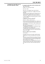
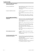
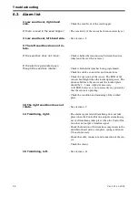
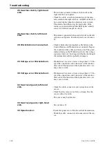
18 Seed fan, low rpm.
- Check that the hydraulic hoses have been correctly
connected to the tractor.
- Check whether the hydraulic oil flow from the tractor
has been correctly set.
- Check the alarm time limits that were programmed
into the Control Station.
- Check the cable, connectors and connections of the
rpm sensor.
- Check the function of the sensor by turning the fan
wheel by hand and also verifying that the sensor LED
lights. The LED should light when the pin on the fan
shaft passes. The distance between the sensor and the
pin should be 1 - 2 mm. Adjust if necessary. A lit
LED, however, is not necessarily any guarantee that
the sensor is operating.
See ”
5.18 Replacing the fan revolution sensor” on
for replacement of the sensor.
- If the alarm is generated intermittently, a likely cause
is incorrect adjustment of the sensor or a defective
sensor.
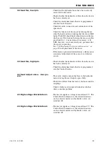
19 Seed fan, high rpm.
- Check whether the hydraulic oil flow from the tractor
has been correctly set.
- Check the alarm time limits that were programmed
into the Control Station.
22 Seed output valve - max. po-
wer.
- This valve, which controls the flow to the hydraulic
motor driving the seed output, opens fully.
- Check the oil flow from the tractor, the hoses and the
couplings.
- Check whether seed output is blocked or whether
there is another problem.
23 High voltage Workstation 1.
- The tractor supplies a voltage of more than 17 V. The
Control Station remains on, but certain functions,
such as electric motors and hydraulic valves, are
switched off.
24 High voltage Workstation 2.
- The tractor supplies a voltage of more than 17 V. The
Control Station remains on, but certain functions,
such as electric motors and hydraulic valves, are
switched off.
Summary of Contents for RAPID RDA S Series
Page 1: ...Ver 2 01 11 2002 900225 en Instructions Seed drill RAPID series RDA 500 800 S No 12 000 12 799...
Page 2: ...2 Ver 2 01 11 2002...
Page 4: ...4...
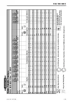
Page 73: ...RDA 500 800 S Ver 2 01 11 2002 73...
Page 75: ...RDA 500 800 S Ver 2 01 11 2002 75 Figure 5 4...
Page 105: ...RDA 500 800 S Ver 2 01 11 2002 105...
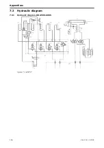
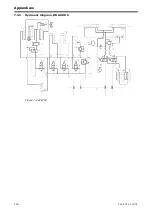
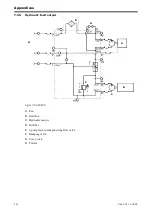
Page 108: ...Appendices 108 Ver 2 01 11 2002 7 3 2 Hydraulic diagram RDA 800 S Figure 7 2 428718...
Page 121: ......


