HuddleSTATION
Vaddio HuddleSTATION - Document Number 342-0692 Rev B
Page 18 of 44
Step 4: Connecting the MicPOD Dock
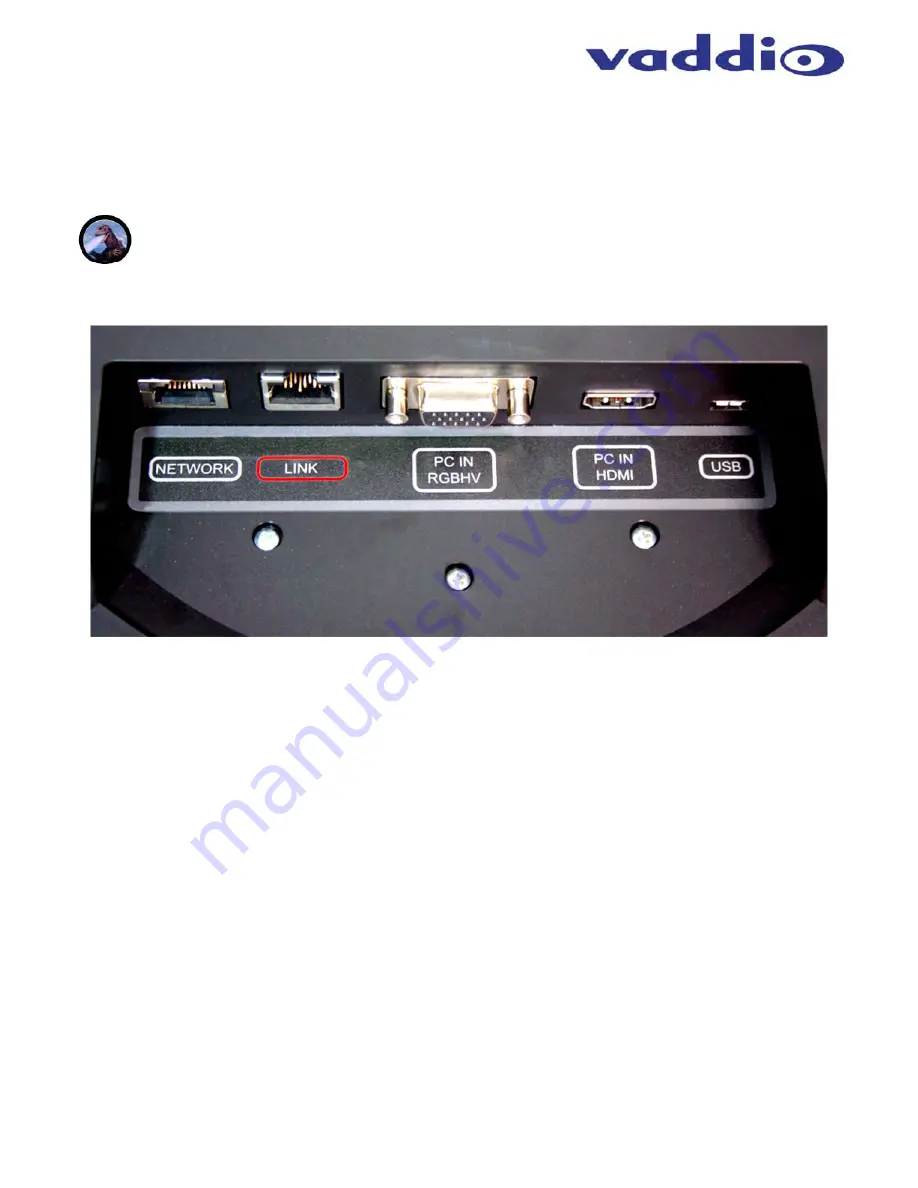
Flip the MicDock upside down to expose connectors and the connector labels. Connect the LINK Cable (provided
Cat-6 SSTP with individually shielded pairs) originating from the Camera/Sound Bar with the connector marked in
red. Power is supplied to the Dock with the LINK cable. Video, audio, and control between the two devices will
be established automatically.
Note:
Please do not plug the LINK cable into the Network RJ-45, incorrect termination is not typically a
good thing, especially when power is involved.
Image: The MicPOD Dock’s Connections
The order of the connections is as follows:
1) LINK
Connection:
As pointed out a few times, connection of the LINK cable between the Camera/Sound
Bar and the MicDock should be made prior to plugging the power supply’s AC power cord into the wall outlet.
Make this connection first. The LINK cable provides power to the MicPOD and automatically establishes
video, audio, and control between the two devices.
2)
All of the rest of the connections (from left to right), are hot pluggable once the LINK cable is connected on
both sides and the power is applied.
Step 5: Docking the PC to MicPOD Dock
Cables required:
A. Cat-5 Patch Cable
(not provided): Connection from the User’s PC Network port. The Network port on
the MicDock is a courtesy 10/100 port for the convenience of set-up.
B. RGBHV (VGA) Cable
*
DE-15M to DE-15M analog video (not provided): If the computer is still using
RGBHV analog video out, then the connection to the MicDock is made with this cable
C. HDMI
Cable
*
(not included). Use this cable if the PC has an HDMI digital video output.
*
Both the RGBHV (VGA) and the HDMI are used as extensions from the PC’s video to the room’s large
screen monitor. The UC application will determine the content that can be transmitted.
D. USB 2.0 Cable
: Type-A Male to Type-B-Micro Male Cable - has to be USB 2.0, 480Mbps rated.


