background image

PRO MIC I/O 


Vaddio PRO MIC I/O - Document Number 342-0569 Rev A 


Page 9 of 16 

System Configuration and Programming: 


PRO MIC I/O: 

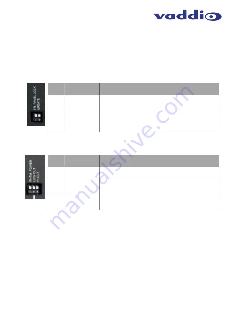
The PRO MIC I/O has a rear dip switch for setting system wide parameters, to include front panel lockout and a 
firmware update mode.  In addition, each audio input channel has a 3-position dip switch for enabling phantom 
power and high/low cut filters.  Gain on the microphones can be set from the front panel rotary knobs for each 
channel.  Default position for the dip switches on the PRO MIC I/O is down. 


Table 1:  PRO MIC I/O System Dip Switch Configuration Settings 


Switch  Function 

Description 

Front Panel Lock 
Out 

This setting disables the four front panel rotary knobs for setting 
audio input level on the integrated microphone preamp.  Dip 
switch 1 in the UP position disables front panel control


Firmware 
Update Mode 

This setting places the PRO MIC I/O in programming mode 
allowing a firmware upgrade through the RS-232 Control Port.  
Dip switch 2 in the up position places unit in firmware update 
mode upon power cycle.   


Table 2:  PRO MIC I/O Channel Dip Switch Audio Settings 


Switch  Function 

Description 


Phantom Power 
Enable 

This setting enables 48VDC phantom power on the input channel.  
Dip 1 in the up position enables phantom power for that channel.


Low Pass Cut 
Filter Enable 

This setting enables a low pass cut filter on the input channel with 
center frequency at 14KHz.  Dip switch 2 in the up position 
enables Low cut channel filter. 

High Pass Cut 
Filter Enable. 

This setting enables a high pass cut filter on the input channel 
with center frequency at 120Hz.  Dip switch 3 in up position 
enables the High cut channel filter. 


Summary of Contents for EASYUSB PRO MIC I/O

Page 1: ...ev A VADDIO EASYUSB PRO MIC I O Professional Microphone Interface with Four 4 Independent Acoustic Echo Cancellers for use with EasyUSB Mixer Amp Part Numbers 999 8520 000 PRO MIC I O Worldwide 999 8522 000 PRO MIC I O Duo Worldwide Installation and User Guide Installation and User Guide ...

Page 2: ...PRO MIC I O Vaddio PRO MIC I O Document Number 342 0569 Rev A Page 2 of 16 Inside Front Cover Blank ...

Page 3: ...nferencing Connection Diagram with PRO MIC I O 7 Step by Step Installation Instructions 8 EasyUSB Mixer Amp Installation 8 Diagram Basic System Connections 8 System Configuration and Programming 9 Table 1 PRO MIC I O System Dip Switch Configuration Settings 9 Table 2 PRO MIC I O Channel Dip Switch Audio Settings 9 Set Microphone Input Gain 10 Image Setting Microphone Levels 10 Firmware Updates 12 ...

Page 4: ...dio coverage pattern The user control buttons such as Mute and Volume are incorporated on top of the device The EasyMic MicPOD connects to the EasyUSB Mixer Amp with single home run of Cat 5 cable providing audio control and power EasyMic Ceiling MicPOD The Ceiling MicPOD is an Echo Canceling Ceiling microphone array with 360 degree audio pick up pattern It includes a plenum rated electronics modu...

Page 5: ...ebsite These documents can be downloaded from www vaddio com free of charge PRO MIC I O 999 8520 000 PRO MIC I O Worldwide Pack out includes One 1 PRO MIC I O Documentation PRO MIC I O Duo 999 8522 000 PRO MIC I O Duo Worldwide Pack out includes Two 2 PRO MIC I O Rack Kit preconfigured 2 PRO MIC I Os side by side with rack kit Documentation The PRO MIC I O is intended to be used in conjunction wit...

Page 6: ...witch associated with system settings Switch 1 locks out front panel again control knobs Switch 2 places PRO MIC I O in firmware upgrade mode upon reboot 2 GPIO Mute Control and Status pins for use with external indicators and controls Inputs are logic low Outputs are open collectors The GPIO Includes a ground and 5 volt power pin to drive external circuits if desired 3 EasyMic Port Serial Port To...

Page 7: ... the Bose ceiling speakers The USB connection to the PC is a UAC device allowing selection of EasyUSB Mixer Amp as the playback and recording device within the operating system Diagram PC Conferencing Connection Diagram with PRO MIC I O Bose Ceiling Speakers Set Each Speaker to 8 Ohm PC with Approved UC Client USB 2 0 UVC Speaker Wire 8 ohm Speaker Wire 8 ohm EasyUSB Mixer Amp PRO MIC I O PRO MIC ...

Page 8: ...into the XLR F connectors on the back panel of the PRO MIC I O STEP 3 Set the desired microphone preamp gain for each microphone input from the front panel of the PRO MIC I O Enable Disable Phantom Power and Filters as Required Optional Accessories The PRO MIC I O has an accessory rack kit Rack Mounting Kit The rack kit provides a method for a single PRO MIC I O to be installed in a 1 RU space pro...

Page 9: ...the integrated microphone preamp Dip switch 1 in the UP position disables front panel control 2 Firmware Update Mode This setting places the PRO MIC I O in programming mode allowing a firmware upgrade through the RS 232 Control Port Dip switch 2 in the up position places unit in firmware update mode upon power cycle Table 2 PRO MIC I O Channel Dip Switch Audio Settings Switch Function Description ...

Page 10: ...syUSB Mixer Amp to the PC with a USB cable STEP 2 Select the EasyUSB Mixer Amp as the default Recording and Playback device within sound manager of the PC STEP 3 Connect the 3 rd party pro microphone to the PRO MIC I O to input channel 1 Enable Phantom Power if required for the microphone see Alternate Step 3 STEP 4 Computer Settings a Open the Sound device panel within Windows b Select the Record...

Page 11: ...ative STEP 5 Plug the next microphone being installed into Input Channel 2 and repeat the process described in step 3 to set the desired gain Important Note It is recommended that only one 1 microphone is plugged or mute other channels into the PRO MIC I O when setting gain levels This is desired to normalize the input level for the automatic microphone mixing function embedded into the PRO MIC I ...

Page 12: ...and don ts of updating Step 2 Place DIP Switch 8 in the UP position on the EasyUSB Mixer Amp This places the system in firmware update mode Power Cycle the unit after enabling DIP switch Make sure the PRO MIC I O is connected to EasyUSB Mixer Amp Step 3 Launch VaddioLoader and select Audio as Product Type In the drop down list go to PRO MIC I O Audio Select desired firmware file to be updated and ...

Page 13: ...one number e mail address shipping address product serial numbers and original purchase order number Describe the reason for repairs or returns as well as the date of purchase See the General RMA Terms and Procedures section for more information RMA s are valid for 30 days and will be issued to Vaddio dealers only End users must return products through Vaddio dealers Include the assigned RMA numbe...

Page 14: ... emission compliance and could void the user s authority to operate this equipment ICES 003 Compliance ICES 003 Issue 4 2004 This digital apparatus does not exceed the Class A limits for radio noise emissions from digital apparatus set out in the Radio Interference Regulations of the Canadian Department of Communications Le présent appareil numérique n emet pas de bruits radioélectriques dépassant...

Page 15: ... F 0 to 40 C 20 to 80 Relative Humidity Power Consumption Maximum 40 watts Dimensions W x D x H PRO MIC I O 1 72 43 7 H x 8 375 212 73mm W x 6 0 152 4mm D Weight PRO MIC I O 1 425643 lbs 0 64666079kg Accessories Rack Mount Kit for single EasyUSB Mixer Amp 998 6000 004 Packages PRO MIC I O Duo is pre configured with 2 PRO MIC I O units in a single RU assembly with two 2 small rack ears Moon in Fron...

Page 16: ...ission is prohibited Specifications and pricing are subject to change without notice Vaddio EasyUSB EasyMic EasyTalk and ClearVIEW are trademarks of Vaddio All other trademarks are property of their respective owners Document 342 0569 Rev A 131 Cheshire Lane Suite 500 Minnetonka MN 55305 www vaddio com Toll Free 800 572 2011 Phone 763 971 4400 FAX 763 971 4464 ...

Reviews:

Related manuals for EASYUSB PRO MIC I/O