background image


20

20

Instrument

Instrument

display

display

Display

Display

code

code

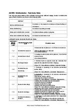
Handheld display fault

Handheld display fault

code

code

Possible cause

Possible cause

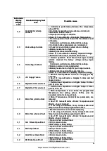
2 , 2

2 , 2

Controller Overtemp

Controller Overtemp
Cutback

Cutback

1.  Controller  is  performance-limited  at  this  temperature

1.  Controller  is  performance-limited  at  this  temperature
(above 85°C).

(above 85°C).
2. Controller is operating in an extreme environment.

2. Controller is operating in an extreme environment.
3. Excessive load on vehicle.

3. Excessive load on vehicle.
4. Improper mounting of 

4. Improper mounting of controller

controller..

5. See 1311 menu Monitor 

5. See 1311 menu Monitor » Controller: Te

» Controller: Temperature.

mperature.

2 , 

, 3 

Undervoltage 

Undervoltage Cutback

Cutback

1. Normal operation. Fault shows that the batteries need

1. Normal operation. Fault shows that the batteries need
recharging.

recharging.

Controller is performance-limited at this voltage.

Controller is performance-limited at this voltage.

2. Controller battery parameters are misadjusted.

2. Controller battery parameters are misadjusted.
3. Check for non-controller s

3. Check for non-controller s ystem drain on battery.

ystem drain on battery.

4. Battery resistance too high.

4. Battery resistance too high.
5. Battery disconnected while driving.

5. Battery disconnected while driving.
6. See 1311 menu Monitor » Battery: Capacitor Voltage.

6. See 1311 menu Monitor » Battery: Capacitor Voltage.
7. Blown B+ fuse or main contactor did not close

7. Blown B+ fuse or main contactor did not close

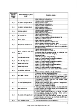
2 , 

, 4 

Overvoltage 

Overvoltage Cutback

Cutback

1.  Normal  operation.  Fault  shows  that  regen  braking

1.  Normal  operation.  Fault  shows  that  regen  braking
currents  elevated  the  battery  voltage  during  regen

currents  elevated  the  battery  voltage  during  regen
braking.

braking.

Controller is performance-limited at this voltage.

Controller is performance-limited at this voltage.

2. Battery parameters are misadjusted.

2. Battery parameters are misadjusted.
3. Battery resistance too high for given regen current.

3. Battery resistance too high for given regen current.

4. Battery disconnected while regen braking.

4. Battery disconnected while regen braking.

5. See 1311 menu Monitor » Battery: Capacitor Voltage.

5. See 1311 menu Monitor » Battery: Capacitor Voltage.

2 , 

, 5 

+5V 

+5V Supply 

Supply Failure

Failure

1. External load impedance on the +5 V supply (pin 26)

1. External load impedance on the +5 V supply (pin 26)
is too low.

is too low.
2.  See  1311  menu  Monitor  »  Outputs:  5  Volts  and  Ext

2.  See  1311  menu  Monitor  »  Outputs:  5  Volts  and  Ext
Supply Current.

Supply Current.

2 , 

, 6 

Digital 

Digital Out 

Out 6 

6 Overcurrent

Overcurrent

1.  External  load  impedance  on  Digital  Output  6  driver

1.  External  load  impedance  on  Digital  Output  6  driver
(pin 19) is too low.

(pin 19) is too low.

2 , 

, 7 

Digital 

Digital Out 

Out 7 

7 Overcurrent

Overcurrent

1.  External  load  impedance  on  Digital  Output  7  driver

1.  External  load  impedance  on  Digital  Output  7  driver
(pin 20) is too low.

(pin 20) is too low.

2 , 

, 8 

Motor 

Motor T

Temp 

emp Hot 

Hot Cutback

Cutback

1.  Motor  temperature  is  at  or  above  the  programmed

1.  Motor  temperature  is  at  or  above  the  programmed
Temperature  Hot  setting  (above  145

Temperature  Hot  setting  (above  145

°C

°C

),  and  the

),  and  the

requested current is being cut back.

requested current is being cut back.
2.  Motor  Temperature  Control  Menu  parameters  are

2.  Motor  Temperature  Control  Menu  parameters  are
mistuned.

mistuned.
3.  See  1311  menus  Monitor  »  Motor:  Temperature  and

3.  See  1311  menus  Monitor  »  Motor:  Temperature  and

Monitor » Inputs: Analog2

Monitor » Inputs: Analog2

4.  If  not  using  a  thermistor,  Temp  Compensation  and

4.  If  not  using  a  thermistor,  Temp  Compensation  and
T

Temp Cutback should be programmed 

emp Cutback should be programmed to OFF

to OFF

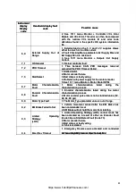
2 , 

, 9 

Motor 

Motor T

Temp 

emp Sensor 

Sensor Fault

Fault

1. Motor thermistor is not connected properly.

1. Motor thermistor is not connected properly.
2.  If  not  using  a  thermistor,  Temp  Compensation  and

2.  If  not  using  a  thermistor,  Temp  Compensation  and
T

Temp Cutback should be programmed 

emp Cutback should be programmed to OFF

to OFF

3.  See  1311  menus  Monitor  »  Motor:  Temperature  and

3.  See  1311  menus  Monitor  »  Motor:  Temperature  and
Monitor » Inputs: Analog2

Monitor » Inputs: Analog2

3 , 

, 1 

Coil 

Coil 1 

1 Driver 

Driver Open/Short

Open/Short

1. Open or short on driver load.

1. Open or short on driver load.
2. Dirty connector pins.

2. Dirty connector pins.
3. Bad crimps or faulty wiring.

3. Bad crimps or faulty wiring.

3 , 

, 1 

Main 

Main Open/Short

Open/Short

1. Open or short on driver load.

1. Open or short on driver load.
2. Dirty connector pins.

2. Dirty connector pins.
3. Bad crimps or faulty wiring.

3. Bad crimps or faulty wiring.

3 , 

, 2 

Coil2 

Coil2 Driver 

Driver Open/Short

Open/Short

1. Open or short on driver load.

1. Open or short on driver load.
2. Dirty connector pins.

2. Dirty connector pins.

3. Bad crimps or faulty wiring.

3. Bad crimps or faulty wiring.

3 , 

, 2 

EM 

EM Brake 

Brake Open/Short

Open/Short

1. Open or short on driver load.

1. Open or short on driver load.
2. Dirty connector pins.

2. Dirty connector pins.

https://www.forkliftpdfmanuals.com/

Summary of Contents for UT13PTE

Page 1: ... No 76002086 Part No 76002086 1 3 1 3 2 0t 3 Wheel Battery Counte 2 0t 3 Wheel Battery Counterbalanced Forklift T rbalanced Forklift Truck ruck Service Manual Service Manual https www forkliftpdfmanuals com ...

Page 2: ...V distributor Service Manuals provide general guidelines for guidelines for maintenance and service and are intended for use by trained and experienced technicians maintenance and service and are intended for use by trained and experienced technicians Failure to properly maintain equipment or to follow instructions contained in the Service Failure to properly maintain equipment or to follow instru...

Page 3: ...r sales agent if you have any questions or comments Please contact your sales agent if you have any questions or comments regarding this manual regarding this manual This electric three wheel forklift truck has passed the requirements for and is approved for operation in This electric three wheel forklift truck has passed the requirements for and is approved for operation in countries adhering to ...

Page 4: ...lic Hydraulic System System 9 9 Main oil pump 9 Main oil pump 9 Multi way valve 10 Multi way valve 10 Pressure adjustment of main Pressure adjustment of main safety valve safety valve 1 11 1 Hydraulic schematic diagram 12 Hydraulic schematic diagram 12 5 5 Lifting Lifting System System 13 13 Mast 14 Mast 14 Lift cylinder 15 Lift cylinder 15 Tilt cylinder 16 Tilt cylinder 16 6 6 Electrical Electric...

Page 5: ...t sound when travelling and changing travelling and changing direction direction Excessive Excessive gear gear backlash backlash Adjust Adjust Excessive Excessive gear gear wear wear Replace Replace Gear noise when travelling Gear noise when travelling Gearbox Gearbox oil oil level level too too low low T Top op up up gear gear oil oil Excessive Excessive gear gear backlash backlash Adjust Adjust ...

Page 6: ...2 2 Structure Structure https www forkliftpdfmanuals com ...

Page 7: ... Hand brake cable connection head connection head has a wear limit of 13 mm Replace Hand brake cable connection head connection head has a wear limit of 13 mm Replace connection head once this limit is exceeded connection head once this limit is exceeded Brake wheel cylinder inlet port replace in the event of Brake wheel cylinder inlet port replace in the event of brake wheel cylinder leakage brak...

Page 8: ...eering wheel forward backward tilt angle can be adjusted according to need See Figure 2 2 adjusted according to need See Figure 2 2 1 1 Steering Steering wheel wheel 3 3 Upper Upper shaft shaft assy assy 8 8 Universal Universal joint joint 10 10 Lower Lower shaft shaft assy assy 12 12 Bearing Bearing 13 13 Snap Snap ring ring 14 14 Steering Steering tube tube 17 17 Steering Steering gear gear 18 1...

Page 9: ...le body 18 is fixed to the rear of the vehicle frame Forces acting on it from th The axle body 18 is fixed to the rear of the vehicle frame Forces acting on it from the ground e ground are carried by the support bearings 10 19 The adjuster nut 8 is used to adjust the are carried by the support bearings 10 19 The adjuster nut 8 is used to adjust the preload preload of the bearings 10 19 The cylinde...

Page 10: ... spindle cannot be moved by hand then rotate nut 8 1 6 moved by hand then rotate nut 8 1 6 to 1 4 turn in to 1 4 turn in the opposite direction the opposite direction Problem Problem Cause Cause Analysis Analysis Remedy Remedy Steering wheel will not turn Steering wheel will not turn Pump Pump damaged damaged or or faulty faulty Replace Replace Clogged or damaged priority valve Clogged or damaged ...

Page 11: ...ton outward so that the outward so that the brake shoe friction plate contacts the brake drum thus causing the brake shoe friction plate contacts the brake drum thus causing the vehicle to vehicle to decelerate or brake At this point the piston s rear chamber is replenished with brake fluid from decelerate or brake At this point the piston s rear chamber is replenished with brake fluid from the re...

Page 12: ...nt braking force force Brake Brake line line leaks leaks oil oil Rectify Rectify and and add add oil oil Air in the brake line Air in the brake line Bleed off air Bleed off air Brake master cylinder not functioning Brake master cylinder not functioning properly properly Rectify or replace Rectify or replace Clogged Clogged oil oil line line Flush Flush Dragging brakes Dragging brakes No No free fr...

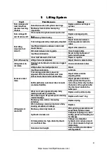
Page 13: ...r which is which is prioritised to ensure operation of the prioritised to ensure operation of the steering system steering system Main oil pump Main oil pump Fault Fault Possible Possible cause cause Corrective Corrective measure measure Oil pump not Oil pump not pumping out pumping out oil oil Low Low oil oil tank tank level level T Top op up up to to specified specified oil oil level level Clogg...

Page 14: ...on Excessive wear clearance between Excessive wear clearance between valve body and valve stem valve body and valve stem Replace stem according to Replace stem according to required clearance required clearance V Valve stem is alve stem is not centred not centred Maintaining valve stem in Maintaining valve stem in neutral position neutral position Cylinder Cylinder seals seals defective defective ...

Page 15: ...the ground the pre und the pressure of the ma ssure of the main safety valve in safety valve needs needs to be increased To do this remove the front floorplate slacken off the main safety valve to be increased To do this remove the front floorplate slacken off the main safety valve lock nut then turn the adjusting screw clockwise to increase the pressure of the main lock nut then turn the adjustin...

Page 16: ...e 4 1 Hydraulic System Diagram Diagram Tonnage Tonnage Item Item 1 3 1 3 t t 1 5 1 5 t t 1 6 1 6 t t 1 8 1 8 t t 2 0 2 0 t t Main relief valve Main relief valve pressure pressure 14 14 MPa MPa 15 5 15 5 MPa MPa 15 8 15 8 MPa MPa 16 5 16 5 MPa MPa 17 5 17 5 Mpa Mpa https www forkliftpdfmanuals com ...

Page 17: ...ate Lubricate Fork carriage side rollers unevenly Fork carriage side rollers unevenly adjusted With the mast tilted side roller adjusted With the mast tilted side roller strikes mast channel when descending strikes mast channel when descending Adjust rollers and side Adjust rollers and side adjusting shims adjusting shims Buffer pad below outer mast does not work Buffer pad below outer mast does n...

Page 18: ...er Inner mast mast 3 3 Chain Chain assembly assembly 4 4 LH LH lift lift cylinder cylinder 5 5 Fork Fork carriage carriage assembly assembly 6 6 Fork Fork assembly assembly 7 7 Tilt Tilt cylinder cylinder 8 8 RH RH lift lift cylinder cylinder Figure 5 1 Mast Figure 5 1 Mast Size and weight of basic mast Size and weight of basic mast lifting height 3 m lifting height 3 m Mast Mast dimensions dimens...

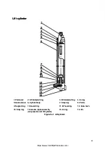
Page 19: ... 7 7 Snap Snap ring ring 8 8 Piston Piston 9 9 Support Support ring 10 ring 10 Guard Guard ring ring 11 11 B7 B7 seal seal ring ring 12 12 Valv Valve e bush bush 13 13 Snap Snap ring ring 14 14 Grease Grease nipple nipple assembly assembly not present on LH lift cylinder not present on LH lift cylinder 15 15 O ring O ring 16 16 Pin Pin Figure 5 Figure 5 2 2 Lift Lift cylinder cylinder https www fo...

Page 20: ...leeve sleeve 10 10 Guide Guide ring ring 1 11 1 B3 B3 seal seal ring ring 12 12 Block Block 13 13 Wire Wire retaining retaining ring ring 14 14 O ring O ring 15 15 Cylinder Cylinder body body 16 16 Piston Piston 17 17 O ring O ring 18 18 Guide Guide ring ring 19 19 Nut Nut 20 20 Cotter Cotter pin pin 21 21 OK OK seal seal ring ring 22 22 O ring O ring Figure 5 Figure 5 3 Tilt cylinder 3 Tilt cylin...

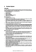
Page 21: ... the ingress of dust or small foreign particles Access to the control logic is very simple and allows substitution or simple and allows substitution or replace replacement ment Steered wheel angle sensor Steered wheel angle sensor The dual motor drive is equipped with a steered wheel angle sensor that transmits angle The dual motor drive is equipped with a steered wheel angle sensor that transmits...

Page 22: ... Indication of faults via LEDs Indication of faults via LEDs Modification of parameters via instrument or handheld unit Modification of parameters via instrument or handheld unit Internal hour meter displayed on instrument Internal hour meter displayed on instrument Memory of the last 10 Memory of the last 10 electrical control alarms electrical control alarms Test function for checking main param...

Page 23: ... 2 See 1311 menu Monitor Battery Capacitor Voltage 2 See 1311 menu Monitor Battery Capacitor Voltage 1 5 1 5 Controller Severe Controller Severe Undertemp Undertemp 1 Controller is operating in an extreme environment 1 Controller is operating in an extreme environment below 40 C below 40 C 2 See 1311 menu Monitor 2 See 1311 menu Monitor Controller Te Controller Temperature mperature 1 6 1 6 Contro...

Page 24: ...e 1311 menu Monitor Outputs 5 Volts and Ext 2 See 1311 menu Monitor Outputs 5 Volts and Ext Supply Current Supply Current 2 2 6 6 Digital Digital Out Out 6 6 Overcurrent Overcurrent 1 External load impedance on Digital Output 6 driver 1 External load impedance on Digital Output 6 driver pin 19 is too low pin 19 is too low 2 2 7 7 Digital Digital Out Out 7 7 Overcurrent Overcurrent 1 External load ...

Page 25: ... Pot 2 See 1311 menu Monitor Inputs Throttle Pot 4 4 3 3 Brake Brake Wiper Wiper High High 1 Brake pot wiper voltage too high 1 Brake pot wiper voltage too high 2 See 1311 menu Monitor Inputs Brake Pot 2 See 1311 menu Monitor Inputs Brake Pot 4 4 4 4 Brake Brake Wiper Wiper Low Low 1 Brake pot wiper voltage t 1 Brake pot wiper voltage too low oo low 2 See 1311 menu Monitor Inputs Brake Pot 2 See 1...

Page 26: ...onitor Motor Motor RPM PM 8 7 8 7 Motor Characterization Motor Characterization Fault Fault 1 Motor characterization failed during the 1 Motor characterization failed during the characterization process characterization process 8 8 8 8 Encoder Characterization Encoder Characterization Fault Fault 1 Encoder characterization failed during the motor 1 Encoder characterization failed during the motor ...

Page 27: ... 000 00 000 24v 1 24v 1 31 L M1 31 L M1 LH travel LH travel motor motor YDQ4 75 4 YDQ4 75 4 HC HC 34v 4 75K 34v 4 75K W W 1 14 1 14 30 XL 30 XL Battery Battery connector connector 95011 01 9 95011 01 9 5038 01 5038 01 160A 150 160A 150 v v 1 1 13 13 SF1 SF1 Brake light Brake light switch switch 24v 3 24v 3 A A 1 1 29 29 FU4 Fuse FU4 Fuse BLX BLX 20A 20A 1 1 Core Core 10A 10A 12 SA5 12 SA5 Red emer...

Page 28: ...24 24 Maintenance Record Maintenance Record Date Operation Date Operation Maintenance Maintenance personnel personnel https www forkliftpdfmanuals com ...

Page 29: ... THE UTILITY LIFT TRUCK and UTILITY YOU CAN TRUST are UTILEV is a registered trademark THE UTILITY LIFT TRUCK and UTILITY YOU CAN TRUST are trademarks in the United States and certain other jurisdictions trademarks in the United States and certain other jurisdictions https www forkliftpdfmanuals com ...

Reviews: