10
but leave an air gap between piping and drain.
No shutoff of any description shall be placed be-
tween safety relief valve and the boiler, or on the
discharge pipes between such safety valve and the
atmosphere. Installation of the safety relief valve
shall conform to ANSI/ASME Boiler and Pressure
Vessel Code, Section IV. The manufacturer is not
responsible for any water damage.
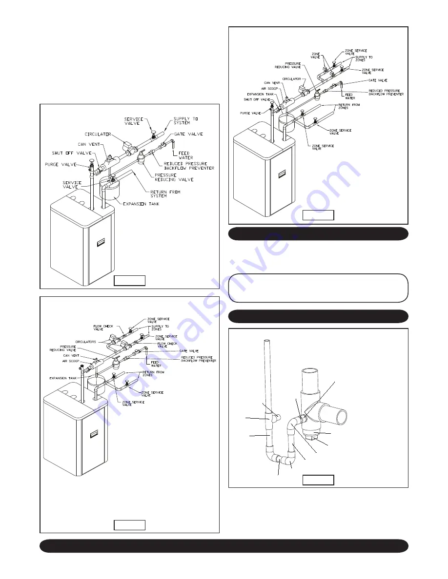
SUPPLY AND RETURN LINES
The packaged boiler unit is set up to receive 1¼”
NPT supply and return piping from top access.
NOTE:
The circulator pump and isolation valves are fur-
nished within a carton inside the boiler cabinet and can be
installed at the installer preferred location.
CONDENSATE DRAIN REQUIREMENTS
Condensate drain line to be pitched down to floor
drain at a minimum of ¼” per foot. An external con-
densate pump (not furnished) may be used if floor
drain is not available. The condensate pump must
be designed for flue gas condensate application.
Figure 9b
MULTIZONE BOILER PIPING
WITH ZONE VALVES
NOTE:
When zoning with circulators, the furnished circulator pump
should be used as one of the zone pumps. Each stripped end of
the electrical wires for the circulator pump inside the junction box
should be taped or wire nutted to prevent short circuits. Unplug the
circulator pump wiring at the integrated boiler control.
MULTIZONE BOILER PIPING
WITH CIRCULATORS
Figure 9a
SINGLE ZONE BOILER PIPING
Figure 8
CONDENSATE DRAIN PIPING
Figure 10
1/2" UNTHREADED
PVC PIPING
2" LONG
1/2" UNTHREADED
PVC ELBOW
1/2" UNTHREADED
PVC PIPING
3 3/4" LONG
1/2" UNTHREADED
PVC ELBOW
1/2" UNTHREADED
PVC PIPING
1 3/8" LONG
1/2" ADAPTER
MALE NPT x SOCKET WELD
PVC PIPING
1 3/8" LONG
1/2" UNTREADED
PVC TEE
1/2" UNTHREADED
PVC PIPING
3 3/4" LONG
TO CONDENSATE DRAIN
(FIELD SUPPLIED)
TO EXHAUST VENT
(2" CPVC)
TO BOILER FLUE OUTLET
(2" CPVC)
2" NPT MALE PVC BUSHING
2" UNTHREADED MALE
x 2" NPT MALE
PVC BUSHING


