USER MANUAL
— Aircraft Interface Device
Page 9 of 13
Rosemount Aerospace Inc. Model 8730L Series
D06429976 Revision 06
UTC AEROSPACE SYSTEMS PROPRIETARY
SUBJECT TO THE RESTRICTION ON THE TITLE OR COVER PAGE.
U.S. Export Classification: EAR: 7E994
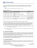
There are five defined model configurations of the AID, each supporting different wireless needs. Model
configuration is accomplished during factory build through the installation radio module internal to the AID
enclosure.
NOTE:
The radios are not accessible and should not be removed by the User.
Table 2: Model Configurations
Manufacturer
Model
Wireless Communications
Radio Module
UTC Aerospace Systems
8730L1-1
No Wireless (Base model)
None
UTC Aerospace Systems
8730L1-2
Cellular
(LTE in North America; 2G/3G elsewhere)
Sierra Wireless MC7354
UTC Aerospace Systems
8730L1-3
Cellular
(LTE in Europe, Middle East, Africa; 2G/3G elsewhere)
Sierra Wireless MC7304
UTC Aerospace Systems
8730L1-4
Wi-Fi (802.11 a/b/g/n)
Advantech EWM-W158F
UTC Aerospace Systems
8730L1-5
Cellular (LTE in North America and EMEA) and Wi-Fi
(802.11 b/g/n)
Sierra Wireless MC7455
and SparkLAN WUBA-
171GN
A SIM card can be installed or removed through the Access Cover on the back of the AID.
The AID has the capability to allow the user to install a CFast card; a solid-state non-volatile data storage device.
The CFast card is a separate LRU (not part of the standard AID configuration) and is accessible through the
Access Cover on the back of the AID for easy removal or insertion. CFast model number 8732D1-1 is available
from UTC Aerospace Systems and has been qualified to operate within the AID operating environment.
NOTE:
The CFast and SIM card are not considered to be hot-pluggable. Ensure the AID is powered off prior to inserting
or removing these devices from the AID.
NOTE:
If the Access Cover on the back of the AID is removed for any reason, reinstall the cover prior to using the AID in
its intended function.
2.2 Mechanical Interfaces
The AID provides mounting provisions (or holes) on the sides of the unit as shown in Figure 1. The 8730L AID is
mounted in the aircraft as a fixed device; it is not movable by the user. The mounting provisions are designed to
interface with a simple U-bracket mounting provision with holes for screws or captive fasteners on the two sides.
Two L-brackets are another potentially simple solution, one on each side.
The AID is cooled by natural convection and by conduction through the mounting provisions. Sufficient clearance
must be provided to permit air flow in the installation. The installation should also be designed to provide a path
for heat to flow through the mounting bracket into the structure.
2.3 Electrical Interfaces
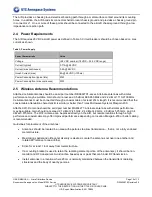
The AID electrical interfaces are made through one 37-pin D-sub pins, (J1), one 37-pin D-sub socket, (J2), and
one 50-pin D-sub pins (J3). The Wi-Fi antenna cable connection and the cellular antenna cable connections are
made with SMA connectors.

