Low Power WiFi Module User Manual V1.3
http://www.tcp232.net
Jinan USR IOT Technology Limited.
Page 5 of 59
LIST OF FIGURES
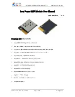
Figure 1.
USR-WIFI232-G Demo
..................................................................................................................
9
Figure 2.
USR-WIFI232-G Pins Map
............................................................................................................
9
Figure 3.
USR-WIFI232-G Mechanical Dimension
..................................................................................
11
Figure 4.
USR-WIFI232-G PCB Symbol Size
...........................................................................................
12
Figure 5.
Suggested Module Placement Region
.....................................................................................
12
Figure 6.
USR-WIFI232-G Evaluation Kit
..................................................................................................
13
Figure 7.
USR-WIFI232-G Order Information
...........................................................................................
14
Figure 8.
USR-WIFI232-G Hardware Typical Application
......................................................................
15
Figure 9.
USR-WIFI232-G Basic Wireless Network Structure
...............................................................
17
Figure 10.
HF-A11 AP+STA Network Structure
.........................................................................................
17
Figure 11.
Multi-TCP Link Data Transmition Structure
.............................................................................
21
Figure 12.
Open Web Management page
...................................................................................................
25
Figure 13.
System Web Page
.......................................................................................................................
25
Figure 14.
Work Mode Page
..........................................................................................................................
26
Figure 15.
STA Setting Page
.........................................................................................................................
26
Figure 16.
AP Setting Page
...........................................................................................................................
27
Figure 17.
Other Setting Page
.......................................................................................................................
27
Figure 18.
Account Page
................................................................................................................................
28
Figure 19.
Upgrade SW page
........................................................................................................................
28
Figure 20.
Restart Page
.................................................................................................................................
29
Figure 21.
Restore Page
................................................................................................................................
29
Figure 22.
STA Interface Debug Connection
..............................................................................................
30
Figure 23.
AP Interface Debug Connection
................................................................................................
30
Figure 24.
“CommTools” Serial Debug Tools
.............................................................................................
31
Figure 25.
“TCPUDPDbg” Tools Create Connection
.................................................................................
31
Figure 26.
“TCPUDPDbg” Tools Setting
......................................................................................................
31
Figure 27.
“TCPUDPDbg” Tools Connection
..............................................................................................
31
Figure 28.
Wireless Control Application
......................................................................................................
32
Figure 29.
Remote Management Application
.............................................................................................
32
Figure 30.
Transparent Serial Port Application
...........................................................................................
33
Figure 31.
USR-WIFI232-G Default UART Port Parameters
...................................................................
33
Figure 32.
Switch to Configuration Mode
....................................................................................................
34
Figure 33.
”AT+H” Instruction for Help
.........................................................................................................
34
Figure 34.
Reflow Soldering Profile
..............................................................................................................
51
Figure 35.
Shipping Information
....................................................................................................................
52
LIST OF TABLES
Table 1
USR-WIFI232-G Module Technical Specifications
.........................................................................
8
Table 2
USR-WIFI232-G Pins Definition
........................................................................................................
9
Table 3
USR-WIFI232-G External Antenna Parameters
...........................................................................
13


