background image

- 5 -

UPC-21

 I

NSTRUCTION 

M

ANUAL


Ultra   Stereo Labs, Inc.

Connect the Center channel speaker terminals to the + and - (ground) audio
input terminals on the IRC-21 as in Fig C. If the center channel is bi-amped,
you must construct a resistor network, as in Fig. D, that sums the high and
low frequency signals, then feed the output of the network to the IRC-21
audio input. You also may connect the IRC-21 input  to the output of a
monitor or a processor.

CONNECT THE AUDIO INPUT LINE

CONNECT THE IRP-20 AC POWER PACK

Connect the provided IRP-
20 AC Power Pack to the
IRC-21 AC terminal using
standard 18-gauge or
greater “zip” cord. (see
TABLE 1 for lengths). Make
sure ther are no loose wire
strands that could touch any
nearby metal and short the
power pack.

   DO NOT SHORT THE
POWER SUPPLY!

Connect the power pack to
a 115 VAC 50/60 Hz outlet.

100k

50k

To IRC-21
+terminal

FIGURE

D

FIGURE C

Cinema Processor Center Channel

AC Power Pack

+    E

Fed From

Center Channel Speaker

OR

Summary of Contents for UPC-21

Page 1: ...UPC 21 Infrared Transmitter Accessories 181 Bonetti Drive San Luis Obispo CA 93401 ph 805 549 0161 fax 805 549 0163 e mail usl uslinc com...

Page 2: ...ty and which is returned to our factory freight paid or serviced by one of our authorized contractors The forgoing warranty is exclusive and in lieu of all other warranties whether expressed or implie...

Page 3: ...RES 3 UPC 21 INSTALLATION 4 AUDIO POWER CONNECTIONS 5 PRELIMINARY LEVEL SETTINGS 6 MOUNTING THE EMITTER 6 INSTALLATION USING TWO IRC 21S 8 FACTS ABOUT INFRARED TRANSMISSION SYSTEMS 9 Illustrations UPC...

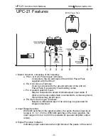
Page 4: ...is connected to a chassis ground this terminal may be left open d Pin 5 6 Audio Input Terminals Balanced differential input One side may be grounded for single ended input 2 Input Range Selector With...

Page 5: ...One IRH 501 or IRH 701 receiver 4 Audio Input level Adjustment Adjust input level so that only the peaks of the audio signal light the LED Signal Presence indicator If the LED is on constantly the au...

Page 6: ...ct the IRC 21 input to the output of a monitor or a processor CONNECT THE AUDIO INPUT LINE CONNECT THE IRP 20 AC POWER PACK Connect the provided IRP 20 AC Power Pack to the IRC 21 AC terminal using st...

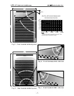
Page 7: ...inches clearance from all surfaces preferably more if at all possible The rear panel is used as a heat sink and the heat must be allowed to dissipate The unit should be mounted to the side of the scre...

Page 8: ...7 Fig F Front mounted emitter top view Fig G Front mounted emitter side view Fig J Rear mounted emitter side view Fig H Rear mounted emitter top view UPC 21 INSTRUCTION MANUAL Ultra Stereo Labs Inc...

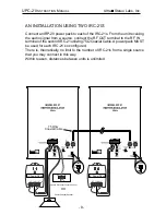
Page 9: ...a source connect the RF OUT terminal to the RF IN terminal of the second IRC 21 utilizing 75 Coaxial Cable A power pack MUST be used for each IRC 21 so configured There is theoretically no limit to t...

Page 10: ...nergy does not penetrate walls The modulated waves remain within the room where the emitter is placed This feature makes it perfect for use in multiplex theatre units and for use in hotel and conventi...

Reviews: