- 4 -
UPC-21 Installation
Unpack the carton and verify that all materials are present.
There should be:
One system manual
One IRC-21 Emitter Panel
One IRP-20 ac Power Pack
One Mounting Bracket composed of 1 ea. IRBS-20 & IRBE-20
Two 10-32 x 5/8 machine screws for attaching the emitter panel to
the mounting bracket.
You will need to supply the following materials:
A small jeweler’s type flat blade screwdriver or trim pot alignment
tool for adjusting the input audio levels.
A medium flat blade screwdriver for attaching the mounting bracket.
Shielded audio cable for connection of the IRC-21 to the program
source.
Eighteen gauge or greater; two or three conductor “zip” cord to
connect the AC power pack to the emitter panel.
Tools and hardware to attach the mounting bracket to the wall
One IRH-501 or IRH-701 receiver.
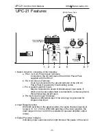
4. Audio Input level Adjustment.
Adjust input level so that only the peaks of the audio signal light the LED
“Signal Presence” indicator. If the LED is on constantly, the audio level
is too high and the channel is clipping.
5. Compression Slope Adjustment.
Adjusts compression from 1:1 to 3:1 with 2:1 at the approximate center
of the range. Improves intelligibility of low level dialog.
6. RF Source Switch.
Selects source of IR RF modulation to be radiated by this emitter panel.
The left switch feeds the local audio modulated rf to the emitter panel.
The right switch connects the emitter panel to an external source, such
as another IRC-21 located in another corner of the auditoruim.
7. RF Input and Output BNC Connectors.
The RF Input connector accepts RF from another IRC-21 for radiation
from this emitter panel. The RF output connector feeds the modulated
rf output from this modulator to another panel.
UPC-21
I
NSTRUCTION
M
ANUAL
Ultra Stereo Labs, Inc.


