background image

14

USI  •  YOUR SOURCE FOR LAMINATION 

LOADING & OPERATING PRESSURE

SENSITIVE FILM

The MRL42" Roll Laminator/Mounter is equipped with the features 
necessary to allow the use of pressure sensitive (cold) film with
release liners for single side lamination. The Waste Rewind will remove
the release liner from the film and wind it onto an empty core, which
can then be disposed.

Turn the heat controls to off and allow machine to cool if necessary
when using cold films.
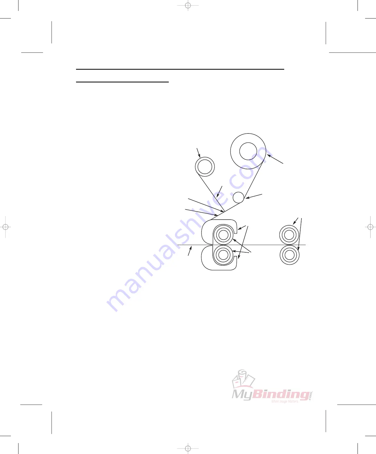
The pressure sensitive film must be mount-
ed on the upper supply mandrel (3" core
adapters are provided if necessary) and
threaded under the idler roller. An empty
film core should be mounted on the waste
rewind mandrel, and the mandrel mounted
onto the laminator. 
A section of scrap substrate that is as least
as wide as the film in use should be started
into the front rollers of the laminator. 
Separate the release liner from the film for
a length of about six inches, and adhere
the exposed portion of the film to the sub-
strate that has been started into the
machine. Bring the end of the release liner
under and up to the Waste Rewind man-
drel, and tape the release liner to the spare
core that has been installed over the man-
drel. The Waste Rewind mandrel may be
rotated by hand to assist in the start up.
Slowly advance the motor of the laminator,
guiding the film and substrate to the rear
rollers, while insuring the release liner is
firmly attached to the Waste Rewind core.

The separation point for the film and
release liner should be between the idler
shaft and the point where the film contacts
the heat shoe. The separation point can be
adjusted by the tension knob on the Waste
Rewind Drive Shaft. If the separation point
is past the point where the film contacts the heat shoe, tighten the 
tension knob slowly until the separation point approaches the idler
roller. If the separation point is too close to the idler roller, then loosen
the tension knob slowly until the separation moves toward the heat
shoe. The tension setting should need very little adjustment once set,
but should be monitored during operation.

Apply a small amount of tension to the upper supply roll if necessary to
clear any wrinkles occurring on the heat shoe. Once the separation
point is set, lamination is performed normally. Care should be taken to
minimize the gap between successive pieces of substrate being 
laminated so that the adhesive from the film is in contact with the lower
roller as little as possible. Cold films utilizing aggressive adhesives will
stick to the laminator’s rollers and potentially wrap around. It is also
recommended to use supply film widths equal to or narrower than the
width of the substrate being laminated.

Note: To encapsulate, run image a second time upside down.

Waste Rewind
Mandrel/Core

Upper Supply Roll

Upper
Idler Roller

Release liner

Separation
Point

Film

Substrate

Front Rollers

Rear Rollers

Heat Shoes


Summary of Contents for MRL Series

Page 1: ...Provided By http www MyBinding com http www MyBindingBlog com USI MRL Series Wide Format Laminators Instruction Manual...

Page 2: ...OPERATION AND MAINTENANCE MANUAL MRL SERIES ROLL LAMINATORS MOUNTERS WIDE F O R M A T LAMINATING Inc Since 1975 USI...

Page 3: ...tion under this warranty shall be limited to the repair or exchange of any part or parts which may prove defective under normal use and service with in two years from the date of shipment and which ou...

Page 4: ...ach covers a different subject heading Each chapter is further broken down into parts Each part contains a detailed discussion covering either an operation or maintenance procedure for your laminator...

Page 5: ...ensitive Film 14 Automatic Reverse Feature 15 Mounting 16 Cooling Fans 17 Inline Slitters 17 Chapter 2 Care And Cleaning Reloading A New Supply Of Film On A Hot Laminator 18 Cleaning The Heat Shoes 19...

Page 6: ...and guards protect operators from such moving parts as the drive chain and sprockets roller ends etc Turn the power switch OFF before walking away or leaving the laminator unattended Before lifting or...

Page 7: ...not place the laminator where the heat shoes will be in the direct path of a room cooling fan air conditioner or similar forced draft Tools necessary to set up your laminator include cutting shears a...

Page 8: ...nd it s skid Should your laminator ever need to be returned for service the foam filled carton ensures safe transit CAUTION Laminator is extremely heavy Two people will be needed to move the machine U...

Page 9: ...e rollers should be turning to heat the rubber rollers evenly Turn the drive switch to the forward position and rotate the speed control knob until the rollers are moving slowly Heat approximately 15...

Page 10: ...roll of film and place it on the laminator as illustrated above Fol low the same steps to load the top supply mandrel See threading diagrams on page 10 FILM SPLICES NOTE When loading your laminating f...

Page 11: ...AM UPPER PULL ROLLER UPPER 2 1 4 SUPPLY MANDREL LOWER IDLER ROLLER DULL SIDE GLOSSY SIDE FRONT HEAT SHOE UPPER LAMINATING ROLLER LOWER PULL ROLLER UPPER IDLER ROLLER GLOSSY SIDE DULL SIDE HEAT SHOE LO...

Page 12: ...ockwise position Be sure that the slitters are rotated up and out of the film s path Turn on the Drive switch and using the threading board push the film web into the laminating rolls This process wil...

Page 13: ...knobs Once the laminator is loaded heated and tension adjusted re install the feed tray HELPFUL HINTS For best results reset tension with EACH new pair of film rolls As the film roll supply becomes l...

Page 14: ...of the substrate stock that you will be laminating push material through the rollers at the same time you will be pushing the film Stop when approximately 1 of board is pertruding out in front of the...

Page 15: ...e rear rollers while insuring the release liner is firmly attached to the Waste Rewind core The separation point for the film and release liner should be between the idler shaft and the point where th...

Page 16: ...hot heat shoes Turn the speed control knob to a slow speed and depress the reverse switch Slowly back the film out of the laminator When clear reload the laminating film WARNING Never use a sharp obj...

Page 17: ...to slowly contact the mounting board just before entering the laminating rollers The machine will apply the mounting pressure as the substrate is run through Mounting Two Step An alternate mounting m...

Page 18: ...ses and lowers the slitters To adjust where the slitters cut first remove the laminating film from the rollers Next raise the slitters to their operating position by rotating the control knob Using an...

Page 19: ...or shears avoid contact with heat shoes or rubber rollers Remove the old cores and replace with new rolls of film Loosen the tension on the film rolls Thread the new web of film around the idler bar a...

Page 20: ...build up Use USI s Laminator Cleaning Kit which contains a foam cleaner for use on the heat shoes rubber rollers a coarse scrubbing pad designed for cleaning rubber rollers and a mesh covered sponge...

Page 21: ...gers Rotate front roller release knob to its full clockwise position Place towel or other padded material on feed table Grab the rear of the heat shoe and rotate it over so that the heat shoe is upsid...

Page 22: ...d Turn the drive switch on and off to advance the rollers and clean each section at a time To clean the lower rollers simply raise the roller lifts WARNING Do not use any sharp metallic objects or ste...

Page 23: ...o high on either or both heat shoes 2 Excessive moisture in the paper being laminated If inks are not dry this may also cause blisters For high moisture content substrates use USI s low temperature fi...

Page 24: ...YOUR SOURCE FOR LAMINATION USI 23 WIRING DIAGRAM MRL 32 42 Only MRL 32 42 Only Left on MRL 32 42 Left on MRL 32 42 MRL 42 Only MRL 42 Only...

Page 25: ...75 75 73 71 49 50 82 74 11 48 4 59 70 47 6 41 42 38 40 46 36 36 45 9 10 6 43 38 36 26 31 32 34 81 58 59 17 16 15 72 14 18 54 19 73 62 63 33 37 36 39 3 1 2 71 35 5 51 60 61 24 7 44 79 66 67 65 64 53 5...

Page 26: ...Board 51 Supply Roll Support Upper Left 52 Terminal Block Marker 53 Supply Roll Support Lower Right 54 Supply Roll Support Upper Right 55 Terminal Block 56 Fuse Holder 57 Screw 6 32x3 8 Phil Pn Hd 58...

Page 27: ...Fort Path Road Madison CT 06443 2264 Sales 800 243 4565 Technical Assistance 800 752 9131 DISTRIBUTION CENTERS Phoenix AZ Madison CT WIDE F O R M A T LAMINATING MRL SERIES ROLL LAMINATORS MOUNTERS Inc...

Reviews: