background image


- 20 - 

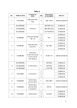
23 

301030014 

pressure 

maintaining valve 

4”-10” 

USCBLR-24\36\48 

24 

301070001 

24”countertop 

char broiler 

intake-tube 

Φ26-503*648 

USCBLR-24 

301070002 

36”countertop 

char broiler 

intake-tube 

Φ26-803*648 

USCBLR-36 

301070003 

48”countertop 

char broiler 

intake-tube 

Φ26-1113*648 

USCBLR-48 

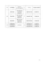
25 

21205001002 

surround 

610*640*203 

USCBLR-24 

21205002002 

910*640*203 

USCBLR-36 

21205003002 

1220*640*203 

USCBLR-48 


Summary of Contents for USCBLR-24

Page 1: ...lers with Lava Rocks Operating Instructions Before you begin please read these instructions carefully to use this product correctly to make the product perform ideally and to avoid hazards Models USCBLR 24 USCBLR 36 USCBLR 48 ...

Page 2: ...for convenient reference and operation This instruction manual is subject to any change without further notice and the manufacturer reserves the right of final interpretation The appliance is designed for commercial purposes not for household use A statement instructing the purchaser to post in a prominent location instructions to be followed in the event the user smells gas This information shall...

Page 3: ...Protection 3 Brief Introduction 3 Manufacturer s Authority and Responsibility 3 Parameter Specifications 4 6 Transport and Storage 7 Installation and Debugging 7 8 Safety Notices and Precautions 10 Operating Instructions 11 13 Cleaning and Maintenance 14 15 Troubleshooting 16 Spare Parts 17 20 Accessories List 21 ...

Page 4: ...har broilers in our company production Which is quality designed reasonably structured conveniently operated durable and conveniently maintained Equipped with a high efficiency stainless steel tubular burner and pilot light convenient to ignite the main fire burner This is hotel supermarket western restaurant and food industry s ideal barbecue product equipment Manufacture s Authority and Responsi...

Page 5: ... 4 Parameter Specifications Outline Dimensions in USCBLR 24 USCBLR 36 ...

Page 6: ... 5 USCBLR 48 ...

Page 7: ... of burners and control method Gas Species Intake tube pressure in W C Per BTU B T U h Total BTU B T U h Nozzle No USCBLR 24 2 pieces Independent control Natural Gas 4 35 000 70 000 36 L P Gas 10 35 000 70 000 50 USCBLR 36 3 pieces Independent control Natural Gas 4 35 000 105 000 36 L P Gas 10 35 000 105 000 50 USCBLR 48 4 pieces Independent control Natural Gas 4 35 000 140 000 36 L P Gas 10 35 00...

Page 8: ...st be disconnected from the gas supply piping system during any pressure testing of that system at test pressures in excess of 1 2psi 3 45kPa Unpacking and Installation Please dispose of all packaging materials and residues after unpacking Check the equipment If it is damaged please keep wrappers and receipts which must be signed by the carrier representative Driver and contact the carriers to pur...

Page 9: ...ator is factory set at 4 Natural Gas W C and 10 L P Gas W C The equipment can only be placed on the incombustible counter top and keep a distance of at least 6 inches 152mm to equipment s both sides and back and distance of at least 4 inches 102mm to the bottom Do not put anything around the equipment or on the counter top and bottom in order to avoid influencing combustion and air circulation Lea...

Page 10: ... you will need to adjust gas pressure regulating valve or contact gas supplier to bargain Fig 2 Unplug pressure gauge after you accomplish pressure testing then install needle type pressure joint screw arbor Important make sure to screw the needle valve to prevent gas escape Debugging It s very important to debug the new stove Through the comprehensive system test of equipment we can ensure functi...

Page 11: ... careful to touch During operation do not directly touch burners and grates Turn off the equipment when repairing maintaining and cleaning If the equipment has any signs of equipment damage gas piping leaks igniter or valves damage or lose product accessories do not operate and call for the service immediately The use of attachments not recommended or sold by the manufacturer may cause fire person...

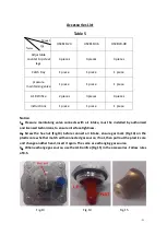
Page 12: ...s extinguished Tips You can use a screwdriver to adjust the height of the flame Fig 4 Igniting the main burner Turn the main fire control valve knob counter clockwise after lighting the pilot light and then the main fire burner is lit by the pilot light The power of the burner increases as angle increases When knob reaches to burner is at maximum power Fig 5 Fig 3 Fig 4 Fig 5 Make sure there is ai...

Page 13: ... for preheating according to the cooking requirement to adjust the flame size Notice When first preheating the furnace will smoke above This is caused by protective lipids on the grates and other parts are heated it is normal and it will be eliminated after it is at maximum power for an hour One side of grate with grease trough Fig 6 and on the other side of grate is flat Fig 7 users can choose a ...

Page 14: ...ithout adjustment but only switching gas Adjust only by authorized and licensed technicians When you converse the gas source exchange the corresponding pressure maintaining valve which installed on air intake See 2 in P19 Adjust air input Remove control panel unscrew damper solid screw Fig 10 revolve damper left to right Fig 11 meanwhile observe flame and adjust an appropriate opening degree Then ...

Page 15: ...r cleaning Warning Wait for the equipment to cool down after the unit has been turned off before you clean Cut off the gas source as not in using If the equipment is not used for a long time clean the surface by wiping it with a soft cloth and place it in a well ventilated area Comprehensively check the equipment at least once every year by authorized and licensed technicians The product is made o...

Page 16: ...ith a scraper 4 Spread cooking oil on the grates open char broiler to evaporate for 45 minutes then close it Warning Do not cover grates in the process of evaporation Daily as need Char Grate Back Support Brace Remove grate until the equipment cools down Take off char grate back support brace clean grease and other crumbs Spread cooking oil Reinstall after cleaning Daily as need Catch tray Pull ou...

Page 17: ...rd a sound of fire 1 Insufficient gas pressure in pipe 1 Contact the local gas supply dept 2 Not match nozzle aperture with gas resources 2 Adjust nozzle diameter 3 Flow of connection pipe is not enough 3 Increase pipe s allowable flow 4 Damper opening degree is too large 4 Adjust damper Yellow flame and black smoke 1 Use bottom gas 1 Change gas 2 Not match nozzle aperture with gas resources 2 Adj...

Page 18: ... by other companies our company has the right to void warranty service Order replacement parts from authorized representatives and after sale service agency Provide the model number serial number and description when ordering components Fig 12 ...

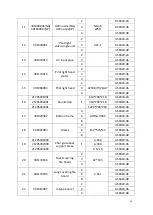
Page 19: ...1 Galvanized flat grommet 4 φ6 φ10 USCBLR 24 6 USCBLR 36 7 USCBLR 48 5 301081006 Galvanized American outside six corner with pad tapping 4 ST4 8 12 5 USCBLR 24 36 48 6 21105001002 Control panel 1 605 185 USCBLR 24 21105002002 905 185 USCBLR 36 21105002002 1215 185 USCBLR 48 7 301140001 Kirsite knob 2 USCBLR 24 3 USCBLR 36 4 USCBLR 48 8 301060001 Needle type pressure joint 1 1 8 27NPT USCBLR 24 36 ...

Page 20: ... 48 16 21205001001 Countertop 1 610 700 218 USCBLR 24 21205002001 910 700 218 USCBLR 36 21205003001 1220 700 218 USCBLR 48 17 301020002 Bottom frame 4 ATOSA 0005 USCBLR 24 6 USCBLR 36 8 USCBLR 48 18 301020003 Grates 4 150 525 22 USCBLR 24 6 USCBLR 36 8 USCBLR 48 19 21205001003 Char grate back support brace 1 L 600 USCBLR 24 21205002003 L 900 USCBLR 36 21205003003 L 1210 USCBLR 48 20 301170004 Shor...

Page 21: ...roiler intake tube 1 Φ26 503 648 USCBLR 24 301070002 36 countertop char broiler intake tube Φ26 803 648 USCBLR 36 301070003 48 countertop char broiler intake tube Φ26 1113 648 USCBLR 48 25 21205001002 surround 1 610 640 203 USCBLR 24 21205002002 910 640 203 USCBLR 36 21205003002 1220 640 203 USCBLR 48 ...

Page 22: ...intaining valve connects with air intake must be installed by authorized and licensed technicians to ensure interface tightness 2 Screw the hex nut Fig 13 before connect air intake ensure gas mark Fig 14 on the plastic core whether match with connected gas source if not then pull out the plastic core and change another head insert it again The same as exchanging gas source 3 When exchange gas sour...

Page 23: ...nce charge But to update some components and necessary maintenance can prolong life length of the products Contact the dealer for assistance In order to avoid confusion please follow the format in figure 12 and table 4 US INC 6890 DISTRIBUTION DRIVE BELTSVILLE MD 20705 USA ...

Reviews: