background image

Ursalink UG87 Quick Start Guide

www.ursalink.com

19

Note

that only gateway with activated built-in Network Server version supports this function.

7.1 Node Parameters

Channel Plan

AS923

Frequency

923.4MHZ, 923.2MHZ

Join Type

OTAA

Device EUI

60C5A8FFFE0003F9

Application EUI

70B3D57ED0007AC2

App Key

1A98A25536993A882154B81551F18A76

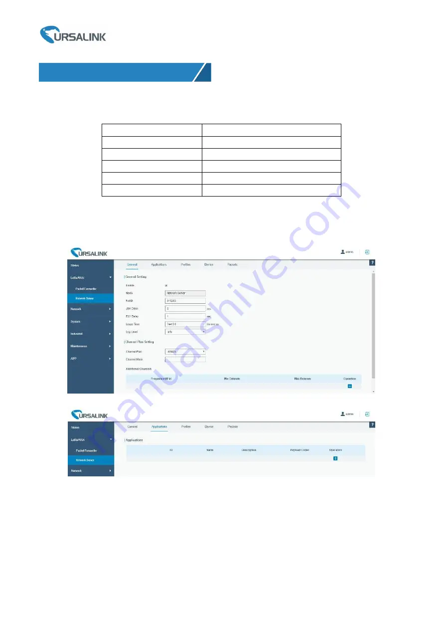
7.2 Network Server Configuration

A. Click “LoRaWAN” → “Network Server” → “General” to configure the general setting.

Note

that the channel plan of the nodes and network server need to be the same.

B. Add a new Application

7. Network Server Testing

Summary of Contents for UG87-In

Page 1: ...1 UG87 In LoRaWAN Gateway Quick Start Guide Ursalink Technology Co Ltd ...

Page 2: ...ctionality and advanced settings please refer to the relevant documents as below Document Description Ursalink UG87 Datasheet Datasheet for the Ursalink UG87 LoRaWAN Gateway Ursalink UG87 User Guide Users can refer to the guide for instruction on how to log in the web GUI and how to configure all the settings The related documents are available on Ursalink website http www ursalink com Declaration...

Page 3: ... UG87 1 Ethernet Cable 1 Power Adapter 2 SIM Card Slots 2 Magnetic Mount Cellular Antennas Default 2 Stubby Cellular Antennas Optional 1 GPS Antenna 1 DIN Rail Kit Default 1 Wall Mounting Bracket Optional If any of the above items is missing or damaged please contact your Ursalink sales representative 1 2 Pin Pluggable Terminal 1 10 Pin Pluggable Terminal 1 Warranty Card 1 Stubby LoRa Antenna 1 Pa...

Page 4: ...ware Introduction 1 Main Cellular Antenna 2 Reset Button 3 LED Indicator Area POWER Power Indicator STATUS Status Indicator Signal Strength Indicator LORA LoRa Indicator VPN VPN Indicator SIM1 SIM1 Status Indicator SIM2 SIM2 Status Indicator 4 Ethernet Port Indicator Orange for data transmission Green for network rate 5 AUX Cellular Antenna 6 GPS Antenna 7 Serial Port I O 8 LoRa Antenna ...

Page 5: ...s registering or fails to register or there are no SIM cards inserted Green Light Blinking slowly SIM1 or SIM2 has been registered and is ready for dial up Blinking rapidly SIM1 or SIM2 has been registered and is dialing up now Static SIM1 or SIM2 has been registered and dialed up successfully Signal Strength Signal 1 2 3 Off No signal Green Light Static Off Off weak signals with 1 10 ASU please c...

Page 6: ...e reset button for about 5 15 seconds Static Green Release the button and wait for system to reboot Reset Blinking Press and hold the reset button for more than 15 seconds Static Green Rapidly Blinking Release the button and wait Off Blinking The gateway is now reset to factory default 2 6 Ethernet Port Indicator Indicator Status Description Link Indicator Orange On Connected Blinking Transmitting...

Page 7: ... F 158 F Relative Humidity 0 to 95 non condensing at 25 C 77 F 3 1 SIM Card Installation 3 1 1 SIM Card Installation A Push the yellow button on the left panel of the B Put SIM card onto the slot then insert the slot gateway and then you will see the SIM card back into the hole slot popping out directly 3 2 Rotate the Antenna into the Antenna Connector 3 Hardware Installation ...

Page 8: ...the gateway and then use 2 pieces of M3 drywall screws to mount the gateway associated with the wall mounting kit on the wall Recommended torque for mounting is 1 0 N m and the maximum allowed is 1 2 N m 3 4 2 DIN Rail Mounting Measured in mm Use 2 pieces of M3 6 flat head Phillips screws to fix the DIN rail to the gateway and then hang the DIN rail on the mounting bracket It is necessary to choos...

Page 9: ...rt wires into the reverse holes the gateway will not start and you must switch the wires into the correct holes 3 6 Protective Grounding Installation A Remove the grounding nut B Connect the grounding ring of the cabinet s grounding wire onto the grounding stud and screw up the grounding nut The gateway must be grounded when deployed According to operating environment the ground wire should be con...

Page 10: ...configure a static IP address manually The following steps are based on Windows 10 operating system for your reference Click Ethernet May have different names Click Properties 4 PC Configuration for UG87 Web GUI Click Search Box to search Control Panel on the Windows 10 taskbar Click Control Panel to open it and then click View network status and tasks ...

Page 11: ...K to finish configuration Double Click Internet Protocol Version 4 TCP IPv4 to configure IP address and DNS server Method 1 click Obtain an IP address automatically Method 2 click Use the following IP address to assign a static IP manually within the same subnet of the gateway ...

Page 12: ... PC is connected to the same network as shown in Section 4 A Open a Web browser on your PC Chrome and IE are recommended type in the IP address and press Enter on your keyboard B Enter the username and password click Login If you enter the username or password incorrectly more than 5 times the login page will be locked for 10 minutes C When you log in with the default username and password you wil...

Page 13: ...llular Connection Take inserting SIM card into SIM1 slot as an example please refer to the following detailed operations A Click Network Interface Cellular Cellular Setting to configure the cellular info B Enable SIM1 C Choose relevant network type Auto 4G First 4G Only 3G First 3G Only 2G First and 2G Only are optional D Click Save and Apply for configuration to take effect ...

Page 14: ...iguration directly If you select 3G First 3G Only 2G First or 2G Only you should manually configure APN Username Password and Access Number UG87 have two cellular interfaces named SIM1 SIM2 Only one cellular interface is active at one time If both cellular interfaces are enabled SIM1 interface takes precedence by default 5 3 Check the Cellular Connection Status 5 3 1 Check the Cellular Connection ...

Page 15: ...dware On the other hand you can check the status of SIM1 indicator If it keeps on green light statically it means SIM1 has dialed up successfully 5 4 Check if Network Works Properly by Browser on PC Open your preferred browser on PC then type any available web address into address bar and see if it is able to visit Internet via UG87 ...

Page 16: ...A Device EUI 60C5A8FFFE0003F9 Application EUI 70B3D57ED0007AC2 App Key 328F2A3F5BA8D0B236459CF06D0512B5 6 2 Configure The Things Network A Gateway Configuration B Applications Configuration Gateway EUI 24E124FFFEF0132E Frequency Plan Asia 920 923MHZ Server ID Switch router ttn opennetworkinfrastructure org 6 Packet Forwarder Testing ...

Page 17: ...G87 Quick Start Guide www ursalink com 16 6 3 Packet Forwarder Configuration A Click LoRaWAN Packet Forwarder General to configure the general setting B Click Radios to configure the center frequency and channels ...

Page 18: ... Click Traffic to view the data communication of UG87 6 4 Check Data Transmission on The Things Network A Click Gateways you can check the Gateways status B Click Applications and select the Applications then go to Data you can find the data from the Node ...

Page 19: ...Ursalink UG87 Quick Start Guide www ursalink com 18 ...

Page 20: ...923 Frequency 923 4MHZ 923 2MHZ Join Type OTAA Device EUI 60C5A8FFFE0003F9 Application EUI 70B3D57ED0007AC2 App Key 1A98A25536993A882154B81551F18A76 7 2 Network Server Configuration A Click LoRaWAN Network Server General to configure the general setting Note that the channel plan of the nodes and network server need to be the same B Add a new Application 7 Network Server Testing ...

Page 21: ...Ursalink UG87 Quick Start Guide www ursalink com 20 C Add a new Profiles for the device ...

Page 22: ...er Configuration Click LoRaWAN Packet Forwarder Radios to configure the center frequency and channels Note that node frequency needs to be included in the channels frequency 7 4 Check the Packets Click LoRaWAN Network Server Packets to check the packets from the node on network server ...

Page 23: ...Ursalink UG87 Quick Start Guide www ursalink com 22 END ...

Reviews: