EM500-SWL User Guide
27
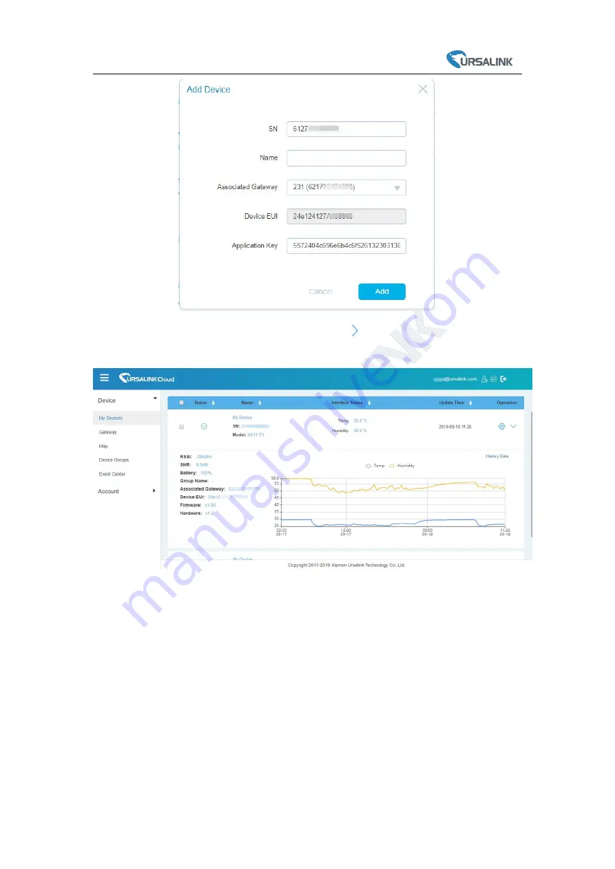
2.After EM500-SWL is connected to Ursalink Cloud, Click
or “History Data” to check the data
on Ursalink cloud.
-END-
Page 1: ......
Page 2: ...re V1 0 Contents 1 Uplink Payload Structure 2 Uplink Packet Example 2 2 Downlink Payload Structure 3 Downlink Packet Example 3 3 Data Types 4 3 1 IPSO Standard Definition 4 3 2 Ursalink Custom Format...
Page 3: ...ne time by using following payload structure 1 Byte 1 Byte N Bytes 1 Byte 1 Byte M Bytes 1 Byte Channel1 Type1 Data1 Channel2 Type2 Data2 Channel 3 Uplink Packet Example Frame N Regular uplink Water L...
Page 4: ...tion ff reserved ff 255 01 1 Custom Format Version 01 1 Version 1 ff 16 61 26 a1 08 75 05 00 35 Channel Type Value ff 255 16 22 Device SN 61 26 a1 08 75 05 00 35 ff 09 01 00 ff 0a 01 01 Channel Type v...
Page 5: ...SO Hex Data Size Data Resolution per Bit Water Level Sensor 3319 77 2 1 Battery 3317 75 1 1 01 75 5a Channel Type Value 01 75 means battery level 5a 90 means 90 03 77 6b 00 Channel Type Value 03 77 me...
Page 6: ...ts of SN e g SN 61 26 a1 01 84 96 00 41 Then DevAddr a1018496 AppKey 5572404c696e6b4c6f52613230313823 NwkSKey 5572404c696e6b4c6f52613230313823 AppSKey 5572404c696e6b4c6f52613230313823 End Software Ver...
Page 7: ...nents do not drop out of the enclosure while opening When closing the lid make sure the lid is fitted the right way so that the enclosure is properly sealed When installing the battery please install...
Page 8: ...Turn ON OFF via Button 12 6 Sensor configuration 12 6 1 Configuration via Smartphone APP 12 6 1 1 Read Configuration 13 6 1 2 Write Configuration 13 6 1 3 Template Settings 14 6 2 Configuration via PC...
Page 9: ...he trend of data change through Ursalink Cloud or thr ough the user s own Network Server 1 2 Features Large measurement range for liquid level measurement Up to 11km communication range Easy configura...
Page 10: ...non condensing Dimension 105 71 69 5 mm Waterproof connector and sensor are not included Mounting Pole wall DIN rail 1 4 Dimensions mm 2 Hardware Introduction 2 1 Packing List 1 EM500 SWL Include cabl...
Page 11: ...separated Front View LoRa Antenna Internal NFC Area Water proof Connector Back View Battery Internal Wall Mounting Holes Pole Mounting Holes 2 Pass the cable through the cap rubber seal and enclosure...
Page 12: ...sludge since it will damage the transmitter It s recommended to fix the transmitter cable with a fixed bracket Note Ensure the gas holes of transmitter do not be blocked while mounting or using it PIN...
Page 13: ...sure Note The pipe can t be placed bend 4 2 EM500 Installation Ensure the location of EM500 is within the communication range of LoRaWAN gateway 4 2 1 Wall Mounting 1 Attach the mounting bracket to th...
Page 14: ...rn ON OFF the Sensor EM500 SWL series can be turned ON OFF via smartphone or computer with NFC Near Field Communication or button Select one of following methods to turn on off the device 5 1 Turn ON...
Page 15: ...Enter the correct password Default password 123456 and wait a few seconds until APP shows Operate Successful Note Keep the two devices close together and do not move them in order that you can get the...
Page 16: ...NFC reader to computer and attach the device to NFC reader 3 Select type as NFC and serial port of NFC reader then click save 4 Device information will be shown on the software 5 Click Power On to tu...
Page 17: ...apidly to reset the device to factory default Over 10 seconds 6 Sensor configuration Ursalink EM500 SWL series sensors can be monitored and configured via NFC technology In order to protect the securi...
Page 18: ...ation of device 2 Attach the smartphone with NFC area to the device until the APP shows Read Successful Note Failing to read can be caused by long distance wrong location or rapid movement 6 1 2 Write...
Page 19: ...re join the network if LoRaWAN paramters are changed Note Failing to write can be caused by long distance wrong location or rapid movement 6 1 3 Template Settings Template settings are used for easy...
Page 20: ...h NFC area to another device 3 Select the template file from Toolbox APP and click Write 4 Enter password of this device and keep the two devices close until the APP shows Write successful 5 Slide the...
Page 21: ...d to read current information of device 3 Attach the device to the NFC reader until Toolbox shows success Note Failing to read can be caused by long distance wrong location or rapid movement 6 2 2 Wri...
Page 22: ...ation or rapid movement 6 2 3 Upgrade 6 2 3 1 Upgrade Locally 1 Download firmware to your computer 2 Go to Maintenance Upgrade in Toolbox 3 Click Browse and select the firmware from computer 4 Click U...
Page 23: ...in order that you can get the best connectivity as possible when upgrading Failing to upgrade can be caused by long distance wrong location or rapid movement 6 2 4 Template and Reset 6 2 4 1 Template...
Page 24: ...oolBox APP Device Settings LoRaWAN Settings Basic Settings OTAA Item Description Default App EUI Enter the application EUI The Network Server receives request and consults the entity associated with t...
Page 25: ...s used to derive the Application Session key 5572404c69 6e6b4c6f526 1323031382 3 Confirmed Mode After sending the attribute data battery packets to the network server the device will resend these pack...
Page 26: ...vice within the current network The 5th to 12th digits number of SN Network Session Key Enter the network session key of the device The network session key specific for the end device It is used by th...
Page 27: ...Box PC LoRaWAN Settings Channel Ursalink ToolBox APP Device Settings LoRaWAN Settings Note Make sure the LoRa channel configuration of EM500 SWL matches the LoRaWAN gateway LoRa frequency configuratio...
Page 28: ...MHz and incrementing linearly by 0 2 MHz to 927 8 8 channels numbered 64 to 71 utilize LoRa 500 kHz BW starting at 915 9 MHz and incrementing linearly by 1 6 MHz to 927 1 For CN470 80 channels numbere...
Page 29: ...revious measured val ue C maximum range If the current measured value exceeds the set value after calculation by the previous formula it is abnorm al and device will measure again Null 7 2 3 Threshold...
Page 30: ...te management and data visualization with the easiest operation procedures 8 1 Ursalink Cloud Registration Register and log in Ursalink Cloud Ursalink Cloud URL https cloud ursalink com login html 8 2...
Page 31: ...of Ursalink Cloud and click Add to add gateway to Ursalink Cloud via SN 3 Check if gateway is online in Ursalink Cloud 8 3 Add EM500 SWL to Cloud 1 Go to Device My Devices and click Add Device Fill in...
Page 32: ...EM500 SWL User Guide 27 2 After EM500 SWL is connected to Ursalink Cloud Click or History Data to check the data on Ursalink cloud END...