background image

DS1092-229


8


4.1.2 

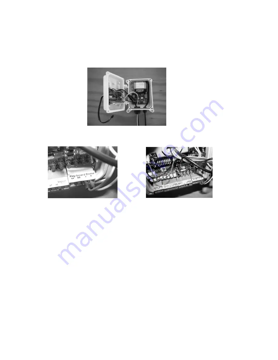
WALL INSTALLATION WITH POWER BOX IP66 REF. 1092/708 

Identify the camera installation point and proceed as follows: 

  Drill holes according to the type of wall (cement, wood, etc.) and the fastening devices used. 


Fasten the connection box to the wall, making sure that the wire grommets are facing downwards. 


Open the Power Box by unscrewing the four screws on the cover corners. 


Insert  in  the  wire  grommets  all  the  cables  needed  for  the  correct  operation  of  the  camera.  For  outdoor 
installations, close hermetically the wire grommets, in order to maintain the IP protection grade.  


Don’t supply the Power Box before the end of the installation 


Connect the RS485  serial line to AA BB terminal pins. 


Conncet the cables of the alarm sensors to A1-A8 terminals of the 1092/709 alarm boar (see instruction on the 
manual of the 1092/708 Power Box) 


Connect the video cable from the video device in use (DVR, monitor, etc.) to the female BNC connector placed 
inside the box, taking care to put the rubber sheath for the protection of the metallic parts, in order to avoid that 
these ones make electrical contact  with internal electronic parts.  


Configure the different  Power Box dip-switches (for details, see the manual of  Power Box 1092/708). 


Close again the  Power Box with the screws previously removed to open it.  

Summary of Contents for Easy Dome 1092/605

Page 1: ...DS1092 229 Mod 1092 EASY DOME CAMERA AHD 20X WITH IR ILLUMINATOR Ref 1092 679 USER AND INSTALLATION MANUAL...

Page 2: ...g functions 13 5 4 5 Preset positions PROGRAM and recalling 13 5 5 Function programming menu 14 5 5 1 Product information menu 15 5 5 2 Display options menu DISPLAY OPTIONS Settings for texts that can...

Page 3: ...s are listed below Designed for easy and quick installation Sony CMOS IMX238 1 2 8 sensor Sensitivity 0 2 Lux color 0 02Lux B W F1 6 Resolution 720p or 1080p selectable 360 degrees horizontal rotation...

Page 4: ...the instructions shown in the installation manual Electrical power A switch for performing maintenance operations on the camera must be included Connect the camera only to the electrical power supply...

Page 5: ...away from rain and dust Do not touch the zoom lens with your fingers If needed use a soft cloth and methylated spirit to remove traces of dust Apply a specific cap to protect the zoom lens when the ca...

Page 6: ...nstalling Urmet Domus 1092 679 These instructions assume that the installer has a good knowledge of installation techniques and is capable of adopting safe installation methods 4 1 EASY DOME MINIMUM C...

Page 7: ...acket providing a suitable protection conduit for the cables Insert the connection cables power video data inside of the bracket until they exit from the opposite side Fasten the bracket to the dome s...

Page 8: ...to maintain the IP protection grade Don t supply the Power Box before the end of the installation Connect the RS485 serial line to AA BB terminal pins Conncet the cables of the alarm sensors to A1 A8...

Page 9: ...the configuration switch Follow the configuration settings for Easy Dome correct functioning see paragraph Dome settings Close the metal cover 4 1 3 CABLES SPECIFICATIONS The system requires 3 types o...

Page 10: ...n Display protocol communication parameters camera address and software version EASY DOME 1092 679 CAMERA CTU20AM108 ADDRESS 1 BAUDRATE 2400 PROTOCOL AUTO VERSION 1 0 S N 064501 INITIALIZING Settings...

Page 11: ...e operation in progress in this way it is possible to start another one or send a command Using a single key Pressing a single key can cause camera action For example the following command will zoom o...

Page 12: ...camera horizontally clockwise and tip it leftwards to turn it anticlockwise If no advanced options are set e g range limits set and enabled the camera can be turned continuously without interruptions...

Page 13: ...y direct commands on the keyboards Presets from 192 to 225 can be managed only by direct commands on the keyboards The manual focusing and iris opening settings cannot be stored The following examples...

Page 14: ...enu simply use CLOSE 1092 621 or IRIS 1092 693 controls also displayed as IRIS in the menus to go back to the previous level menu If you want to exit definitively any level menus simply use the CLOSE...

Page 15: ...and crosshair Option Value Explanation CAMERA NAME SETUP This operation makes it possible to assign a name to the Easy Dome Pressing IRIS twice accesses the screen page for naming of the device COORD...

Page 16: ...s for tilt function are reversed V SCAN STILL NA NOT AVAILABLE AUTO FOCUS Z PTZ OFF If activated the Dome will automatically perform the control of images focusing If activated with PTZ the Dome will...

Page 17: ...ON the Dome tilt limit increases of 5 degrees going from 90 to 95 SPEED LIMIT ON OFF If active with ON limits Dome speed of movement to half the maximum speed IRLED CONTROL It permits to set the mode...

Page 18: ...ing mode enter the serial number below S N 211237 Device serial number RETURN Exits the OSD menu IR LED CONTROL submenu of the CONTROL OPTIONS menu Option Value Explanation IR LED MODE AUTO ON OFF Sel...

Page 19: ...D FOCUS submenu Option Value Explanation ZOOM SPEED 1 8 NOT AVAiLABLE DIGITAL ZOOM ON OFF NOT AVAiLABLE AF SENSITIVITY LOW HIGH This option allows to change the sensitivity level of the Auto Focus fun...

Page 20: ...ing time is fixed to 1 50 second o The autoiris opening is manually varied in the BRIGHT LEVEL menu o Gain control is off 0 dB SLOW SHUTTER ON OFF This function if enabled ON increases the dome sensit...

Page 21: ...180 vertical rotation H MIRROR ON OFF If enabled ON this function allows to see the images horizontally flipped 180 horizontal rotation D N MODE AUTO COLOR B W The opening and closing of the IR filter...

Page 22: ...age STORED CALL PRESET This operation allows to recall a stored preset DELETE PRESET This operation allows to delete a stored preset After selecting the preset to be deleted press IRIS and confirm aga...

Page 23: ...le to define the action kind the number to which it is associated the movement speed and the dwelling time see below RUN A VECTORSCAN This option allows to start the selected VectorScan DELETE A VECTO...

Page 24: ...n and press again IRIS to confirm the pattern storage RUN This option allows to store the patterns Press IRIS and select with the joystick the frame to be stored press again IRIS to confirm the patter...

Page 25: ...define the TILT end position With the joystick select the zone end position and confirm with IRIS The coordinates will be automatically stored by the dome NAME This option permits identification of th...

Page 26: ...1 64 VECTORSCAN 1 7 PATTERN 1 6 PANSCAN 1 AUTOSCAN 1 Allows to select the action to be carried out after power on The selectable value associated to the single action changes according to the previou...

Page 27: ...d see below Option Value Explanation PAN START POSITION 0 0 359 9 0 0 90 0 This option allows to store the PAN TILT start position coordinates for the zone By pressing IRIS and selecting with the arro...

Page 28: ...U OF FUNCTION PROGRAM This function determines a continuous movement between two points selected by user Option Value Explanation START POINTER Allows to memorize the coordinates before starting funct...

Page 29: ...es previously described functions ACTION PATTERN PANSCAN AUTOSCAN PRESET VECTORSCAN Allows to select the action to be associated to each of the available alarm contacts NUMBER PRESET 1 64 VECTORSCAN 1...

Page 30: ...asswords Master and Operator to access the menu PASSWORD MANAGEMENT The MASTER password first level allows to access USER ADMIN menu and enables the password holder Administrator to lock unlock action...

Page 31: ...ion allows to make again active all the dome factory settings RESOLUTION 720P 25 720P 30 1080P 25 1080P 30 This option permits to select the video resolution DOME RESTART This option permits to restar...

Page 32: ...ogram presets CALL PRESET ON OFF If enabled ON this option allows the user to use presets CAMERA SETUP ON OFF If enabled ON this option allows the user to change the dome operation parameters SET PATT...

Page 33: ...the parameters about Protocol and Baud Rate Dip Switch Protocol 1st Dip 2nd Dip Auto OFF OFF DYNACOLOR ON OFF Dip Switch Baud rate 3rd Dip 4th Dip 2400 OFF OFF 4800 ON OFF 9600 OFF ON 19200 ON ON ON 1...

Page 34: ...OFF OFF OFF ON OFF OFF OFF 18 OFF ON OFF OFF ON OFF OFF OFF 19 ON ON OFF OFF ON OFF OFF OFF 20 OFF OFF ON OFF ON OFF OFF OFF 21 ON OFF ON OFF ON OFF OFF OFF 22 OFF ON ON OFF ON OFF OFF OFF 23 ON ON O...

Page 35: ...74 PRESET PRESET 74 ENTER Enables the white balance in outdoor mode 75 SHOT SHOT 75 ENTER Enables the ATW Auto Tracing White balance function 75 PRESET PRESET 75 ENTER Enables the white balance One P...

Page 36: ...8 alarm input activation 179 SHOT SHOT 179 ENTER Simulates the N 9 alarm input activation 180 SHOT SHOT 180 ENTER Simulates the N 10 alarm input activation 181 SHOT SHOT 181 ENTER Simulates the N 11...

Page 37: ...e with heating and fan 30 55 C Working temperature inside housing 0 50 C Electricity 24Vac 3A 50 60Hz Consumption 10W Included power supply YES Function Value On screen menu YES Preset number 128 Vect...

Page 38: ...uto flip YES Waterproof level IP66 Remote control Value Interface RS485 Protocol Pelco D Data rate 2400bps 4800bps 9600bps 19200bps selezionabili tramite dip switch IMPORTANT NOTE Technical features m...

Reviews: