sec. 4e
−−−−
11
2 VOICE - Technical Manual
CALL FORWARDING DEVICE
4.
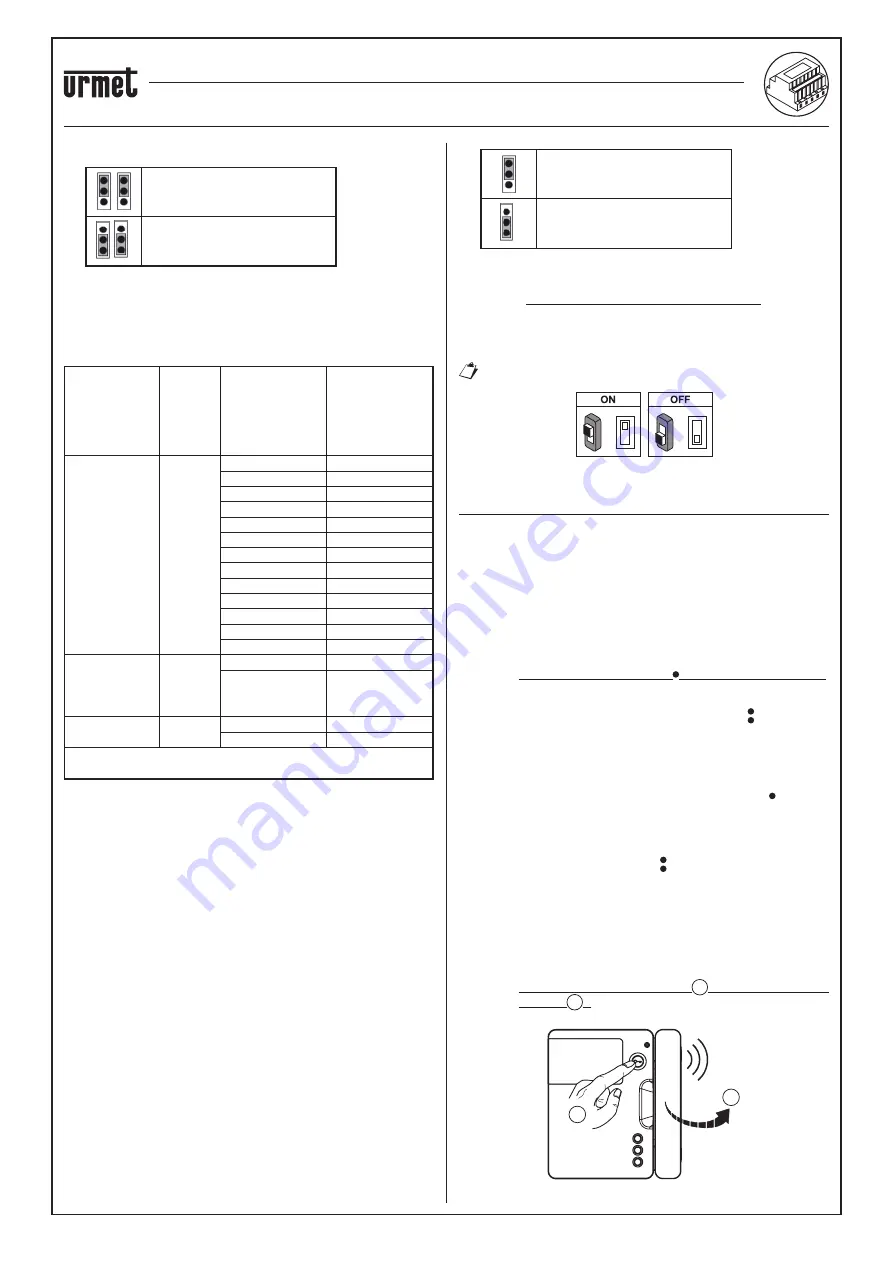
Jumpers to de
fi
ne the type of power supply to the device.
Power from Bus line
(DEFAULT)
Power from local external power
supply
5.
+/- 24V terminals
:
external local power supply terminals.
Certain 2Voice system con
fi
gurations allow the Call Forwarding
Device to be powered directly from the BUS line of the system
without using a local power supply ref. 1083/24; a few limit
examples are listed in the following table:
Type of cable
Max
no. of
internal
stations
per riser
column
No. of video
door phones/
door phones
mod. Miro with
Call Forwarding
Device
Max no. of Call
Forwarding
Devices
powerable from
the system BUS
(*)
2Voice /
HVV05-F da
1 mm
2
/ AWG17
128
≤
12
all
13÷19
11
20÷23
10
24÷27
9
28÷31
8
32÷35
7
36÷39
6
40÷43
5
44÷47
4
48÷51
3
52÷55
2
56÷59
1
60÷63
0
Cat5 / telephone
wire pair with
Ø 0.6 mm
(AWG22)
64
≤
18
3
19÷32
2
Wire, 1 mm
2
(AWG17)
32
≤
12
all
13÷16
11
(*) Any excess devices must be powered off local
power supplies ref. 1083/24
It is possible, however, to calculate the exact number of Call
Forwarding Devices (without power supply) that can be arranged
within the system, knowing the type and the number of indoor stations
that you wish to use:
1. In the case of a system with 2Voice cable or HVV05-F cable 1
mm
2
(AWG17) or single wire, 1 mm
2
(AWG17)
CFSAmax = [127 – PI1 – (2*PI2) – CF] / 8
2. In the case of a system with Cat5 cable or telephone wire pair
with Ø 0.6 mm (AWG22)
CFSAmax = [127 – PI1 – (2*PI2) – CF] / 30
Where:
CFSA
: is the result that expresses the maximum number (rounded
down) of Call Forwarding Devices without power supply
that can be powered off the system BUS.
PI1
: number of indoor stations (video door phones/door
phones) mod. Miro or video door phones mod. Aiko/Folio
present in the system.
PI2
:
number of indoor stations (video door phones mod. Modo
or PABX interfaces) present in the system.
CF
: Number of Call Forwarding Devices present in the
system.
6.
LINE IN, LINE OUT terminals
:
connection to the system bus.
7.
Jumper Z
:
line termination setting.
Line termination must be activated on a device connected at the
end of a line without a new section restarting from the LINE OUT
terminals.
Termination on
(DEFAULT)
Termination off
8.
Dip switch CODE:
they de
fi
ne the number of the apartment in the
column:
no. 1:
do not move, it should remain set to OFF
(if set to ON
and then back to OFF, it will return the column address to its
default value);
no. 2 to 8: they de
fi
ne the apartment number in the column
For no. 2 to 8 dip-switch settings, refer to the System
2Voice manual.
=
=
ON
ON
PROGRAMMING AN INTERCOM CALL FROM THE
INDOOR STATION TO THE SMARTPHONE
After ensuring that the Call Forwarding Device is con
fi
gured correctly,
go to the indoor station to be programmed as the caller.
According to the model of indoor station used, there are 2
different ways of carrying out programming
:
A) Programming with handset on-hook (Mod. Miro).
1. Make a call from the outdoor station to the indoor station.
2. On your smartphone, answer the call and leave the
conversation
open.
3. On the indoor station:
a. press and hold the button for more than 5 seconds;
programming start is con
fi
rmed by the yellow LED starting
to
fl
ash at a slow rate;
b. now press the key to be programmed (e.g. ) for at least 3
seconds until a con
fi
rmation tone is heard.
4. On your smartphone, open the pedestrian access door.
5. On the indoor station:
a. a beep sound will con
fi
rm that programming has been
successfully completed;
b. to quit the programming mode, hold the key down for
more than 5 seconds.
6. On your smartphone, end the current conversation.
7. To check the programmed function:
a. lift the handset off the hook at the indoor station and press
the programmed key (e.g. );
b. check for the presence of the call on your smartphone and
of a voice feedback when you answer.
B) Programming with handset off-hook.
1. Make a call from the outdoor station to the indoor station.
2. On your smartphone, answer the call and leave the
conversation
open.
3. On the indoor station:
a. hold the door opener button 1 pressed and lift the
handset 2 . A tone coming from the indoor station will
indicate that programming is in progress.
BEEP
2
1
•
•
CALL FORWARDING DEVICE FOR 2 VOICE SYSTEM Ref. 1083/58
DEVICE INSTALLATION


