6
Description
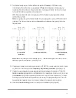
1-2� Input level should be set to 0 dB� (i�e� the 0 dB LED should be lit most of the time during the audio
programme� The +12 dB LED indicator should not be lit at any time�)
3-4� Parametric MLC control makes it possible to fine tune the frequency response, compensating for
the effects of different metal types and configurations�
There are 4 parametric curves starting from; 2 kHz, 1 kHz, 500 Hz and 100 Hz� These set the
frequency at which the metal loss correction control starts to compensate� The function is powerful,
however, excessive compensation can lead to signal limiting in the treble range� If signal limiting occurs,
the red peak LED illuminates�
5�
System Diagnostics verify the integrity and function of the loop driver - inputs, output and the loop
condition�
Use: Set the switch on the front panel to right position� A built-in 1�6kHz signal pulses at 2 seconds
intervals at 0 dB, regardless of the adjusted sensitivity�
If input and output LEDs flashes in unison, the loop driver functions are verified�
If only the input LEDs flashes it indicates that the loop is not connected or the current potentiometer
needs to be readjusted��
Switch to left position Off, for normal use�
6�
Loop current controls set the output current, i�e� the field strength of the loop�
7�
Loop current LED bar graph indicates the level of the loop current, not the field strength� The field
strength is measured using a Field Strength Meter, like Univox FSM 2�0�
8�
Peak (clip) LEDs illuminate when there is insufficient voltage to maintain a constant loop current�
Momentary short term voltage clipping is unlikely to be audible in hearing aids, but if clipping occurs for
any length of time (the Peak LED remains on) the audio quality will suffer�
Peak clipping will typically occur when using long thin wires, 2-turn loops and for signals with high
frequency spectrum, like modern music� Speech has a small amount of high frequency content� Strong
compensation from the parametric MLC control may increase the risk of clipping�
Note:
use ULD for simulation guidance before installation and commissioning�
9,13,14 Loop Monitor, supports headphone (9) and speaker outputs (14) representing the sound quality of
the loop� Volume control for both headphones and speakers, is set by the potentionmeter (13)�
10�
Power LED verifies power supply connection
11�
4 pin DC Supply socket for secure connection of Univox approved power supplies 90-260VAC, 50-60Hz,
only� Connect the power to the amplifier before connecting to the network, otherwise there is a risk of
sparking�
12�
Loop scew terminals for Master and Slave loop connection
A.
MISCELLANEOUS OUTPUTS PHOENIX SCREW
TERMINAL (6 connectors/screws)
14�
Monitor speaker connector
Pin 1+2 (2=GND), speaker output 8-32 Ω
15�
Auxiliary DC power output 15V-24V depending on model
Pin 3+2 (2=GND), DC 12-18V output, 100mA

