10
System setup
Start-up procedure
1� Disconnect all input and output connections�
2� Each loop must be securely isolated (particularly to safety-ground and other loop
connections)� Verify the resistance of each loop (approximately 1-3 Ohm)�
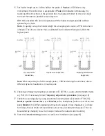
3� Set all level controls to minimum setting:
• System Diagnostics
(5)
= Off (switch to left position)
• Parametric MLC
(4)
= 2kHz (switch to right position)
4� Connect the
Power supply
(11)
and verify
Power LED
indication
(10)
5� Activate
System Diagnostics
by sliding the switch to the right� Input level bar graph
peaks
(2)
to 0dB � Output bar graph
(7)
does not indicate�
6� Connect
Master loop
(12)
and adjust the output level, making sure input and output
bar graphs indicate in unison� Note: a 2-turn loop is often more efficient� See next page�
7� Check field strength for all loop segments using a field strength meter, e�g FSM 2�0�
Verify low field strength directly above wires and high in between segments (peaks to
approximately -2dB)� If not, there might be a local short circuit between wires�
8� Disconnect Master loop and connect Slave loop
(12).
Repeat the procedure for
Slave loop
�
9� Basic function of the loop system is now verified� Turn
System Diagnostics
off, by
sliding the switch to the left�
10� Reconnect Master slave�
Input connection and adjustments
11� Set all level controls to minimum setting:
• System Diagnostic
(5)
= Off (switch to left position)
• Parametric MLC
(4)
= 2kHz (switch to right position)
12� Connect the main audio source to the amplifiers input (B, C or D)
13� Adjust input level (1) to 0dB at input bar graph (2)� If using a 1kHz pulsed sine wave
signal, simply set to 0dB�
Output connection and adjustments
14� Field strength setting: Start with the highest efficiency connection,
I)
2-turn serial
connection, in junction box
�


