background image

Page 17

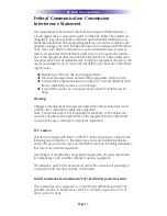
Federal Communication Commission
Interference Statement

This equipment has been tested and found to comply with the limits for a
Class B digital device, pursuant to part 15 of the FCC Rules. These limits are
designed to provide reasonable protection against harmful interference in a
residential installation. This equipment generates, uses and can radiate radio
frequency energy and, if not installed and used in accordance with the instruc-
tions, may cause harmful interference to radio communications. However,
there is no guarantee that interference will not occur in a particular installa-
tion. If this equipment does cause harmful interference to radio or television
reception, which can be determined by turning the equipment off and on, the
user is encouraged to try to correct the interference by one more of the follow-
ing measures:

Reorient or relocate the receiving antenna.

Increase the separation between the equipment and receiver.

Connect the equipment into an outlet on a circuit different from
that to which the receiver is connected.

Consult the dealer or an experienced radio/TV technician for
help.

Warning!

Changes or modifications not expressly approved by the manufacturer could
void the user's authority to operate the equipment.
Note : The manufacturer is not responsible for any Radio or TV interference
caused by unauthorized modifications to this equipment. Such modifications
could void the user's authority to operate the equipment.

FCC Caution

This device complies with Part 15 of the FCC Rules. Operation is subject to the
following two conditions: (1) this device may not cause harmful interference,
and (2) this device must accept any interference received, including interference
that may cause undesired operation.

Any changes or modifications not expressly approved by the party responsible
for compliance could void the authority to operate equipment.

The antenna(s) used for this transmitter must not be co-located or operating in
conjunction with any other antenna or transmitter.

Federal Communication Commission (FCC) Radiation Exposure Statement

This remote device is approved as a hand-held and hand-operated only
portable (relative to hand) device which is normally operated at 20 cm
from a person’s body.

KP-4000 N

ETWORK

K

EYPAD

Summary of Contents for KP-4000

Page 1: ...KP 4000 Installation Manual Network Keypad ...

Page 2: ...TE CONTROL INC SHALL NOT BE LIABLE FOR OPER ATIONAL TECHNICAL OR EDITORIAL ERRORS OMISSIONS MADE IN THIS MANUAL The information in this manual may be subject to change without prior notice Complete Control is a registered trademark of Universal Remote Control Inc All other brand or product names are trademarks or registered trademarks of their respective companies or organizations 500 Mamaroneck A...

Page 3: ... Power 7 In Wall Installation 8 CCP MAC Address Discovery 9 Displaying the Settings Screen 10 Adjusting Sleep Settings 10 Button Light Settings 10 Setting Date and Time 10 Sound 11 Adjusting Brightness 11 System 11 Network 11 Factory Default 12 Exit 12 Frequently Asked Questions 13 Specifications 13 USA Limited Warranty Statement 14 Regulatory Information to the user 15 Declaration of Conformity 1...

Page 4: ...lashers affix to the Infrared sensors on the front panels of your client s compo nents The Flashers relay com mands to components The flash ers plug in to the MRX 1 rear flasher line outputs via their 10 foot cables The MRX 1can also connect to components with rear panel IR Inputs via its adjustable IR Line Outputs 2 The MRX 1 receives com mands from the Network then controls IR RS 232 and Relay c...

Page 5: ...t Scenes for URC Lighting via RFTX 1 Your client can fully control the lighting in their home without expensive black boxes and exotic wiring A lighting system can be as simple as a single URC RF lamp dimmer on a lamp that they d love to control without getting out of a chair The KP 4000 s optional RFTX 1 transmitter directly controls URC RF Dimmers and Switches Your client can brighten dim and re...

Page 6: ... advantage that a single CAT 5 cable to the KP 4000 supplies all connections needed However should you be installing a KP 4000 in a system where it is convenient to run an additional two conductor wire to the KP 4000 for power you may power a KP 4000 from any 12V wall adapter with a 1 amp rating 12v wall adapters may be separately ordered from URC Option 1 PoE Switch Page 3 KP 4000 NETWORK KEYPAD ...

Page 7: ...nections to IP devices MRX 1 and the internet connect a CAT 5 cable RJ 45 to the LAN connection on the rear of the KP 4000 and plug the other end into the Router Option 3 No PoE 12 Volt Power Supply 1 Connect the CAT 5 cable RJ45 to the LAN connection on the rear of the KP 4000 2 Plug the other end of the CAT 5 cable to the PoE Injector which will power the KP 4000 3 Connect the PoE injector not i...

Page 8: ... Labels Tear off the 2nd label and stick it to your Job Documentation indicating which room the KP 4000 is installed You ll need the MAC address when you program the KP 4000 Connections In most installations you will power the KP 4000 via a single CAT 5 cable connected to the network The KP 4000 is PoE so you can power it from either a PoE power injector or any PoE switch LAN PoE RJ 45 Plug an Eth...

Page 9: ...side the wall cavity To connect use the following terminations to the KP 4000 Page 6 KP 4000 NETWORK KEYPAD Data Connect the white wire which is connected to the Tip of the 3 5mm plug GND Connect the black wire which is connected to the bottom sleeve base of the 3 5mm plug 5V Connect the red wire which is connected to the ring of the 3 5mm plug IR Emitter Connection Should you need to drive an IR ...

Page 10: ... available You must run an additional two conductor cable to the KP 4000 to utilize this feature Connect a spliced power adapter 12Volt 1AMP with the polarity Positive Negative connected cor rectly 12V 1A Connect to the conductor of a 12V 1 Amp DC wall adapter GND Connect to the conductor of a 12V 1 Amp DC wall adapter KP 4000 NETWORK KEYPAD ...

Page 11: ...retro fit box not included into the wall 2 Make connections for IR Out RFTX 1 LAN or Power Supply For connections refer to page 5 3 Next secure KP 4000 onto p ring or retro fit box with the 4 included screws 4 Finally attach the magnetic cover plate to the four screws secured into the KP 4000 Two Gang Wall Box KP 4000 Magnetic cover plate In Wall Installation ...

Page 12: ...Network Keypad from the Remotes section and the properties window opens Note Adding a MRX 1 base station to communicate with a KP 4000 is recommended 5 Within the Network Information field press the Discover button to select the unique MAC address of your unit 6 The Discover window opens to reveal KP 4000 s connected to the network Highlight the MAC address which matches the KP 4000 s label Then p...

Page 13: ...ion Adjusting Sleep Settings Conserve energy by configuring the keypad to fall asleep after a specified amount of time Select a time from the drop down list Button Light Settings Conserve energy by opting to turn off the LED lighting behind the buttons Setting Date and Time Your KP 4000 may have been programmed to display the date or time on the touch screen If you need to you can adjust the time ...

Page 14: ... by touching and dragging the volume control here Adjusting Brightness Simply touch and drag the brightness slider to the desired level System The System Information screen displays data about your KP 4000 s operating system memory etc Network The Network screen displays network information about your KP 4000 and the network it is connect to Factory Default WARNING Only use this button when instru...

Page 15: ...the memory of the KP 4000 to the factory condition All your programming will be lost Exit When you have finished adjusting Settings simply tap the EXIT button to return to normal operation Page 12 KP 4000 NETWORK KEYPAD ...

Page 16: ...ION URC DOES NOT WARRANT THAT THE URC SOFTWARE IS BUG FREE OR ERROR FREE OR THAT THERE ARE NO ERRORS BUGS IN THE URC SOFTWARE URC warrants that at the time of purchase the URC equipment and the URC software complied with all applicable regulations and policies of the Federal Communications Commission FCC regarding electromagnetic interference caused by electronic computing devices and to the exten...

Page 17: ...t prepaid in its original packaging or packaging affording adequate protection to URC at 420 Columbus Avenue Valhalla NY 10595 It is end user s responsibility to backup any macro programming artwork software or other materials that may have been programmed into the unit It is likely that such data software or other materials will be lost during service and URC will not be responsible for any such ...

Page 18: ...OR ANY THIRD PARTY THE LIMITATIONS OF LIABILITY MAY NOT APPLY TO END USER IN WHOLE OR IN PART WHERE SUCH ARE RESTRICTED LIMITED OR EXCLUDED BY APPLICABLE LAW AND SUCH SHALL APPLY TO THE MAXIMUM EXTENT PERMITTED BY APPLICABLE LAW URC SHALL NOT BE HELD RESPONSIBLE FOR THE STATEMENTS MADE BY OTHERS SOME STATES OR JURISDICTIONS DO NOT ALLOW THE EXCLUSION OR LIMITATION OF INCIDENTAL OR CONSEQUENTIAL DA...

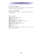
Page 19: ...P 4000 Press and hold Main Mute for 3 seconds then select the Factory Default button Specifications Microprocessor 190MHz RISC Memory 128MB Flash Devices Supports up to 255 Devices Pages Supports up to 255 Pages on each Device Macro Capability Up to 255 steps Network One 10 100 Ethernet port PoE LCD 3 5 inch 320x240 Weight 9 84 oz Size 5 75 x 4 7 x 1 8 Power Standard PoE Injector PoE Switch or 12V...

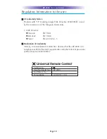
Page 20: ...he receiver is connected Consult the dealer or an experienced radio TV technician for help Warning Changes or modifications not expressly approved by the manufacturer could void the user s authority to operate the equipment Note The manufacturer is not responsible for any Radio or TV interference caused by unauthorized modifications to this equipment Such modifications could void the user s author...

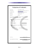
Page 21: ...y 1 EMC Directive Emission EN 55022 Immunity EN 55024 Power EN 61000 3 2 3 Declaration of Conformity Hereby Universal Remote Control Inc declares that this KP 4000 is in compliance with the Essential requirements and other relevant provisions of EMC Directive 2004 108 EC KP 4000 NETWORK KEYPAD Certification Type No Model No KP 4000 Batch Serial No Power Rating 12 0V 1 0A ...

Page 22: ...h complies with the requirements of EMC Directive 2004 108 EC issued bythe Commission of the European Community Compliance with these directives implies conformity to the following European Community EMC Directive EN 55022 EN 55024 EN 61000 3 2 EN 61000 3 3 List of test reports and or certificate verified compliance with the standards above Date of issue December 22 2010 Name and signature of auth...

Page 23: ...Page 20 KP 4000 NETWORK KEYPAD ...

Page 24: ...500 Mamaroneck Avenue Harrison NY 10528 Phone 914 835 4484 Fax 914 835 4532 www universalremote com OCE 0080A Rev 04_RH ...

Reviews: