Vision™ Installation Guide
6
Unitronics
Pinouts
The pinouts below show PLC port signals.
To connect a PC to a port that is set to RS485, remove the RS485 connector, and connect the PC to
the PLC via the programming cable. Note that this is possible only if flow control signals are not used
(which is the standard case).
RS232
RS485**
Controller Port
Pin #
Description
Pin #
Description
Pin #1
1*
DTR signal
1
A signal (+)
2
0V reference
2
(RS232 signal)
3
TXD signal
3
(RS232 signal)
4
RXD signal
4
(RS232 signal)
5
0V reference
5
(RS232 signal)
6*
DSR signal
6
B signal (-)
*Standard programming cables do not provide connection points for pins 1 and 6.
**When a port is adapted to RS485, Pin 1 (DTR) is used for signal A,
and Pin 6 (DSR) signal is used for signal B.
RS232 to RS485: Changing DIP Switch Settings
The port set to RS232 by factory default.
To change the settings, first remove the Snap-in I/O Module, if one is installed, and then set the
switches according to the following table.
RS232/RS485: DIP Switch Settings
Switch Settings
1
2
3
4
5
6
RS232*
ON
ON
ON
OFF
ON
OFF
RS485
OFF
OFF
OFF
ON
OFF
ON
RS485 with
termination**
ON
ON
OFF
ON
OFF
ON
*Default factory setting
**Causes the unit to function as an end unit in an RS485 network
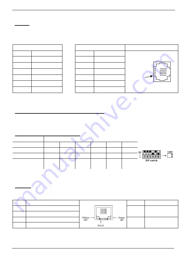
Ethernet
Implement communications via TCP/IP, such as MODBUS over TCP.
RJ45 Connector Pinout
Ethernet LEDS
Pin #
Description
LED
Function
1
T+ = Positive transmit signal
Green
(LNK)
ON when link
exists
2
T- = Negative transmit signal
3
R+ = Positive receive signal
Yellow
(ACT)
Blinks during
RX/TX
6
R- = Negative receive signal


