background image


UniStream

®

 PLC 


Wiring Guidelines  

In order to ensure that the device will operate properly and to avoid electromagnetic 

interference: 


Use a metal cabinet. Make sure the cabinet and its doors are properly earthed. 


Use wires that are properly sized for the load. 


Use shielded twisted pair cables for wiring High Speed and Analog I/O signals. 
Use shielded cables for wiring thermocouple and RTD signals. 

In either case, do not use the cable shield as a signal common / return path. 


Route each I/O signal with its own dedicated common wire. Connect common wires 

at their respective common (CM) points at the controller. 


Individually connect each 0V point and each common (CM) point in the system to the 

power supply 0V terminal, unless otherwise specified. 


Individually connect each functional ground point ( ) to the earth of the system 

(preferably to the metal cabinet chassis). 

Use the shortest and thickest wires possible: less than 1m (3.3’) in length, minimum 

thickness 14 AWG (2 mm

2

). 


Connect the power supply 0V to the earth of the system. 


Earthing the cables' shield:  

Connect the cable shield to the earth of the system (preferably to the metal cabinet 

chassis). Note that the shield must be connected only at one end of the cable; it is 

recommended to earth the shield at the PLC-side.  

Keep shield connections as short as possible. 

Ensure shield continuity when extending shielded cables. 

N

OTE


For detailed information, refer to the document System Wiring Guidelines, 

located in the Technical Library in the Unitronics’ website. 


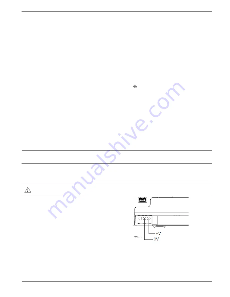
Wiring the Power Supply


The controller requires an external power supply. 


In the event of voltage fluctuations or non-conformity to voltage power supply 

specifications, connect the device to a regulated power supply. 

Connect the +V and 0V terminals as 

shown in the accompanying figure.


Connecting Ports 


Ethernet 

CAT-5e shielded cable with RJ45 connector 


USB Device 

Use a standard USB cable, Type mini-B 


USB Host 

Standard USB Type-A plug 


Unitronics 


Summary of Contents for UniStream PLC Series

Page 1: ...to tuned PID data tables data sampling and Recipes UniApps Access edit data monitor troubleshoot debug and more Security Multi level password protection Alarms Built in system ANSI ISA standards COM Options Built in ports 2 Ethernet 1 USB host 1 USB device port Add on ports UAC CB available by separate order 1 CANbus port may be added to all models RS232 485 ports according to model technical spec...

Page 2: ...between B10 B5 and B3 Feature B10 Pro B5 Standard B3 Basic I O Expansion via Uni I O Yes No Remote I O Expansion via Ethernet I O Adapter URB Up to 8 1 VFD 32 2 MicroSD Yes No Add on COM modules 3 2 System Memory 6GB 3GB 3GB MODBUS Slaves Unlimited Up to 8 Ethernet IP Scanners 16 1 Ethernet IP Adapters 32 8 Web Server Yes No No SQL Client Yes No No MQTT Yes PID Loops 64 2 Data Sampler Trends Yes N...

Page 3: ... and regulations This product should be installed only by qualified personnel Failure to comply with appropriate safety guidelines can cause severe injury or property damage Do not attempt to use this device with parameters that exceed permissible levels Do not connect disconnect the device when power is on Environmental Considerations Ventilation 10mm space is required between the device top bott...

Page 4: ... Closed Covers the Confirm button and the USB Host port 6 Bottom Door Closed Covers the internal door protecting the battery and microSD slot 7 Uni COM Jack Connection port for Uni COM CB modules Shipped covered leave cover in place when not in use Top View 8 Ethernet ports Two ports for Ethernet communications 9 Input Output connection points Model dependent Present in models with built in I O co...

Page 5: ... Battery Holder The battery is supplied installed the user must remove the pull tab during installation These are available by separate order Installation Space Considerations Allocate space for The controller I O wiring Access to ports jacks and the microSD card slot Any modules that will be installed ensure you allow space to install uninstall modules Module dimensions and installation instructi...

Page 6: ...ower off the battery must be connected First Use The battery is protected by the PLC s bottom and inner door The battery is supplied installed inside the unit with a plastic tab preventing contact Pull out this tab before using the device Battery Installation and Replacement Use proper precautions to prevent Electro Static Discharge ESD while servicing the battery Caution To preserve back up value...

Page 7: ...rmed while power is OFF Use over current protection such as a fuse or circuit breaker to avoid excessive currents into the power supply connection point Unused points should not be connected unless otherwise specified Ignoring this directive may damage the device Double check all wiring before turning on the power supply Caution To avoid damaging the wire use a maximum torque of 0 5 N m 5 kgf cm D...

Page 8: ...st and thickest wires possible less than 1m 3 3 in length minimum thickness 14 AWG 2 mm2 Connect the power supply 0V to the earth of the system Earthing the cables shield Connect the cable shield to the earth of the system preferably to the metal cabinet chassis Note that the shield must be connected only at one end of the cable it is recommended to earth the shield at the PLC side Keep shield con...

Page 9: ...f certain I Os may be adapted via wiring and software settings USC Bx R38 USC Bx T42 Wiring the Digital Inputs The digital inputs are arranged in two isolated groups I0 I9 share common CM0 I10 I23 share common CM1 Each group may be wired together as sink or source Inputs I10 I17 can be configured as either normal digital inputs or as high speed inputs that can receive high speed pulse signals from...

Page 10: ...Normal digital Channel 3 Channel 4 I14 I15 I16 I17 Quadrature Phase A Phase B Phase A Phase B Pulse Direction Pulse Direction Pulse Direction Pulse Pulse Normal digital Pulse Normal digital Input wiring sink Input wiring source High Speed Input wiring sink High Speed Input wiring source NOTE Use sink input wiring to connect a sourcing pnp device Use source input wiring to connect a sinking npn dev...

Page 11: ...des voltage or current You can set each input independently The mode is determined by the hardware configuration within the software application Note that if for example you wire the input to current you must also set it to current in the software application Voltage Differential Single ended Current 2 wire 3 wire 4 wire Unitronics 11 ...

Page 12: ...ces according to the device s installation guide 3 Unscrew and remove the mounting brackets taking care to support the device to prevent it from falling during this procedure The information in this document reflects products at the date of printing Unitronics reserves the right subject to all applicable laws at any time at its sole discretion and without notice to discontinue or change the featur...

Reviews: