UIS-08TC Installation Guide
4
Unitronics
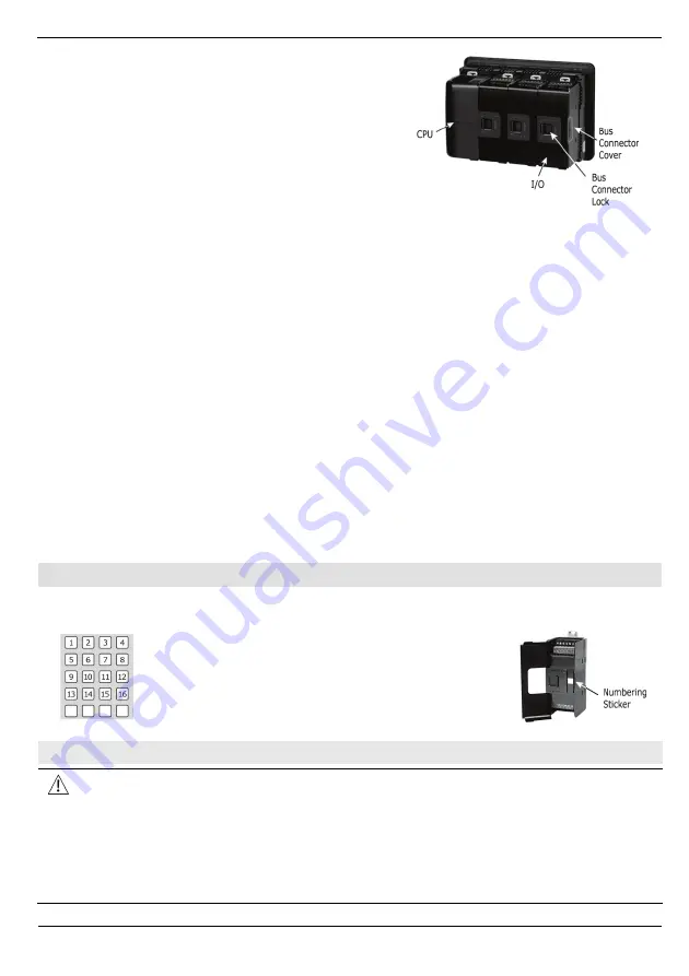
5. Slide the Bus Connector Lock all the way to
the left as shown in the accompanying figure.
6. If there is already a module located to its
right, complete the connection by sliding the
Bus Connector lock of the adjacent unit to the
left.
7. If the module is the last in the configuration,
leave the I/O bus connector covered.
Removing a Module
1. Turn off the system power.
2. Disconnect the I/O terminals (#2,3,7,8 in the diagram).
3. Disconnect the Uni-I/O™ module from the adjacent units: slide its Bus Connector Lock
to the right. If there is a unit located on its right, slide the lock of this module to the
right as well.
4. On the Uni-I/O™ module, pull the top DIN-rail clip up and the bottom clip down.
5. Open the door of the Uni-I/O™ and hold it with two fingers as shown in the figure on
page 3; then pull it carefully from its place.
Installing Uni-I/O™ modules onto a DIN-rail
To mount modules onto a DIN-rail, follow steps 1-7 in Installing a Uni-I/O™ Module onto a
UniStream™ HMI Panel on page 3.
In order to connect the modules to a UniStream™ controller, you must use a Local
Expansion Kit.
These kits are available with and without power supplies, and with cables of varying
lengths. For complete information, please refer to the installation guide of the relevant
Local Expansion Kit.
Numbering Modules
You can number modules for reference purposes. A set of 20 stickers is provided with
every CPU-for-Panel; use these stickers to number the modules.
The set contains numbered and blank stickers
as shown in the figure to the left.
Place them on the modules as shown in the
figure to the right.
Wiring
This equipment is designed to operate only at SELV/PELV/Class 2/Limited Power
environments.
All power supplies in the system must include double insulation. Power supply
outputs must be rated as SELV/PELV/Class 2/Limited Power.
Do not connect either the ‘Neutral’ or ‘Line’ signal of the 110/220VAC to device’s 0V
point.
Do not touch live wires.


