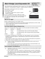


UniStream™Uni-I/O™
Unitronics
3
Connecting the Base Unit
1. Check the unit to which you will connect the
Base Unit to verify that its Bus Connector is
not covered.
2. Hold the Base Unit as shown in the
accompanying figure, and plug it into the last
device installed on the back of the HMI panel.
3. Click the top and bottom clips into the Guide
Tunnel of the last device.
Connecting the End Unit
1. Push the End Unit onto the DIN-rail until the clips located at the top and bottom of the
unit have snapped onto the DIN-rail.
2. Install Uni-I/O™ modules to the right of the End unit. Please refer to the specific
Installation Guide of each Uni-I/O™ module.
3. Slide the Bus Connector Lock of the first module all the way to
the left.
4. Link the units by plugging the RJ45 of the End Unit’s cable into
the port on the bottom of the Base Unit.
5. If you are using a:
UAG-XKPxxx with power supply, connect it to a power source
as described on page 4.
UAG-XKxxx without power supply, earth it.
Do not connect the cable to any device other than the Base Unit.
Do not connect the Base Unit’s cable port to any other cable or device.
Wiring
This equipment is designed to operate only at SELV/PELV/Class 2/Limited Power
environments.
All power supplies in the system must include double insulation. Power supply
outputs must be rated as SELV/PELV/Class 2/Limited Power.
Do not connect either the ‘Neutral’ or ‘Line’ signal of the 110/220VAC to device’s 0V
point.
Do not touch live wires.
All wiring activities should be performed while power is OFF.
Use over-current protection, such as a fuse or circuit breaker, to avoid excessive
currents into the UAG-XKPxxx supply port.
Unused points should not be connected (unless otherwise specified). Ignoring this
directive may damage the device.
Double-check all wiring before turning on the power supply.
Caution
To avoid damaging the wire, use a maximum torque of 0.5 N·m (5 kgf·cm).
Do not use tin, solder, or any substance on stripped wire that might cause the
wire strand to break.
Install at maximum distance from high-voltage cables and power equipment.


