Unitronics UAG-XK series Installation Manual Download Page 2

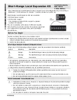
Short-Range Local Expansion Kit Installation Guide  


Unitronics 


Do not allow debris to fall inside the unit during installation. 


Install at maximum distance from high-voltage cables and power equipment. 


Kit Contents 


Item 

Qty 

UAG-XKxxx  UAG-XKPxxx 

Local Expansion Base Unit 

√ 

√ 

Local Expansion End Unit with 

an integrated xxx cm cable. 

√ 

Local Expansion End Unit with a 

power supply and an integrated 

xxx cm cable. 

√ 

Terminal Block 

√ 

√ 


Kit Diagram  


Bus connector  

Base Unit plug 

Clips 

Base Unit’s cable port 

RJ45 connector  

End Unit LED indicators  

DIN-rail clips, top and bottom 

End Unit I/O bus connector 

I/O Bus - Left side connector 

10  Model-dependent: 


UAG-XKPxxx power supply connector 


UAG-XKxxx earth point connector 


Installation Space Considerations 

Allocate space for the Base Unit and End Unit according to the dimensions in the kit’s 

technical specifications. Also, consider the space required to install and connect them, as 

shown in the following Installation instructions. 


Installation 


Turn off system power before connecting or disconnecting any modules or devices. 


Use proper precautions to prevent Electro-Static Discharge (ESD). 

This kit enables you to connect a UniStream™ controller to a row of Uni-I/O™ modules 

located on a DIN-rail. To do this, you must: 


Connect the Base Unit to the last device installed on the back of the HMI panel. This may 

be the CPU-for-Panel, a Uni-COM™ module, or another Uni-I/O™ module. 


Connect the End Unit to the first module in a row of Uni-I/O™ modules. 


Link the End Unit into the Base Unit via the connecting cable. 


If you are using a:  


UAG-XKPxxx with power supply, connect it to a power source 


UAG-XKxxx without power supply, earth it. 


Summary of Contents for UAG-XK series

Page 1: ...ied danger causes physical and property damage Warning The identified danger could cause physical and property damage Caution Caution Use caution All examples and diagrams are intended to aid understanding and do not guarantee operation Unitronics accepts no responsibility for actual use of this product based on these examples Please dispose of this product according to local and national standard...

Page 2: ...tion Space Considerations Allocate space for the Base Unit and End Unit according to the dimensions in the kit s technical specifications Also consider the space required to install and connect them as shown in the following Installation instructions Installation Turn off system power before connecting or disconnecting any modules or devices Use proper precautions to prevent Electro Static Dischar...

Page 3: ...e 4 UAG XKxxx without power supply earth it Do not connect the cable to any device other than the Base Unit Do not connect the Base Unit s cable port to any other cable or device Wiring This equipment is designed to operate only at SELV PELV Class 2 Limited Power environments All power supplies in the system must include double insulation Power supply outputs must be rated as SELV PELV Class 2 Lim...

Page 4: ... shown in the accompanying figure 7BRemoving the Expansion Cable 1 Turn off the system power 2 Unplug the cable from the Base Unit 3 To remove the Base unit pull the top clip up and the bottom clip down and pull it slowly away until the plug disengages 4 To remove the End unit Locate the Bus connector lock of the Uni I O module connected to the End Unit and slide it to the right Pull the End Unit ...

Reviews: