background image

EXF-RC15 Installation Guide


Unitronics 


Relay Outputs 


Increasing Contact Life Span 


To increase the life span of the relay 
output contacts and protect the device 
from potential damage by reverse EMF, 
connect: 

  A clamping diode in parallel with each 

inductive DC load 

  An RC snubber circuit in 

parallel with each inductive AC 
load 


Power Supply 

The model requires an external 24VDC power supply. 


  The power supply must include double insulation. Outputs must be rated as  

SELV/PELV/Class 2/Limited Power. 


  Use separate wires to connect the functional 

earth line (pin 3) and the 0V line (pin 2) to the 
system earth ground. 

  Install an external circuit breaker. Guard against 

short-circuiting in external wiring. 

  Double-check all wiring before turning on the 

power supply. 


Do not connect either the ‘Neutral’ or ‘Line’ signal 
of the 110/220VAC to device’s 0V pin. 

  In the event of voltage fluctuations or non-

conformity to voltage power supply specifications, 
connect the device to a regulated power supply. 


Earthing the model 

To maximize system performance, avoid electromagnetic interference by: 

  Mounting the model on a metal panel. 

  Connect each common and ground connection directly to the earth ground of your system. 

For ground wiring use the shortest and thickest possible wire.


Summary of Contents for EXF-RC15

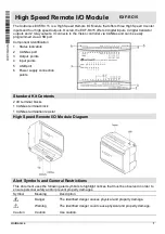
Page 1: ...s 2 CANbus port 3 Output points 4 Input points 5 USB port 6 Power supply connection points Standard Kit Contents 2 I O terminal blocks 1 CANbus terminal block 1 CANbus termination resistor High Speed Remote I O Module Diagram Alert Symbols and General Restrictions This document uses the following alert symbols to highlight notices that must be observed in order to ensure personal safety and or pre...

Page 2: ...l in areas with excessive or conductive dust corrosive or flammable gas moisture or rain excessive heat regular impact shocks or excessive vibration in accordance with the standards given in the product s technical specification sheet Do not place in water or let water leak onto the model Do not allow debris to fall inside the model during installation Ventilation 10mm space required between model...

Page 3: ...nto the terminal to ensure a proper connection 4 Tighten enough to keep the wire from pulling free Input or output cables should not be run through the same multi core cable or share the same wire Allow for voltage drop and noise interference with I O lines used over an extended distance Use wire that is properly sized for the load The model and I O signals must be connected to the same 0V signal ...

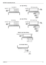
Page 4: ...EXF RC15 Installation Guide Unitronics 4 npn Input Wiring Input wiring HSC input wiring pnp Input Wiring Input wiring HSC input wiring Shaft encoder Input Wiring npn Outputs Wiring ...

Page 5: ... the functional earth line pin 3 and the 0V line pin 2 to the system earth ground Install an external circuit breaker Guard against short circuiting in external wiring Double check all wiring before turning on the power supply Do not connect either the Neutral or Line signal of the 110 220VAC to device s 0V pin In the event of voltage fluctuations or non conformity to voltage power supply specific...

Page 6: ... sole discretion and without notice to discontinue or change the features designs materials and other specifications of its products and to either permanently or temporarily withdraw any of the forgoing from the market All information in this document is provided as is without warranty of any kind either expressed or implied including but not limited to any implied warranties of merchantability fi...

Reviews: