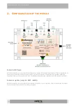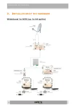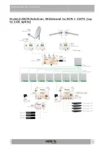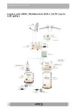
Optical Headend (Ref. 4002 & 4003)
5
Signal Quality LED:
The signal quality LED shows you the quality of the signal with different colors.
Orange
Color: Signal level is too low. In this case you should amplify the signal with an
external amplifier.
Green
Color: Signal level is within the AGC supported range.
Red
Color: Signal level is too high. You need to attenuate the signal with external
attenuator(s).
Solid LED:
Slope is OK
Blinking LED
: Slope is out of range
Set DC Supply and Laser Diode:
With this switch you can set the DC (18V) supply to the RF input and switch off the Laser
Diode (LD) in order to measure each optical signal separately. To measure the signal strength
of a certain wavelength, you need to switch off both other Laser Diodes.
Don't forget to switch all LDs on after measurement.
The LED is
off
if no DC is supplied to the RF input and if no DC is supplied to the Laser Diode.
If no DC is supplied to the laser diode, the related signal is not converted into an optical signal.
Please make sure to switch on at least the laser diode for proper operation.
The LED is
green
if the Laser diode is switched on and the related output voltage off.
The LED is
orange
if the Laser diode is switched on the related output voltage is supplied to
the RF input.
The LED is
green
/
orange
blinking if DC is supplied to the RF input and the device recognized
a short circuit.
Optical output:
The optical transmitters each have an optical output power of +9 dBm per wavelength.
For REF.4003, make sure to set the select the right number of splits using the split switch.


