CHAPTER 2: GENERAL SETUP
MODEL HF2 2 kHz HIGH FREQUENCY RESISTANCE WELDING POWER SUPPLY
2-4
990-057
HF2 Welding System Maximum Secondary Loop Resistance
To use the HF2 Weld Control and HF2 Weld Transformer system to its maximum capability, the
Maximum Secondary Loop Resistance must not exceed the values listed in the preceding table.
Exceeding these maximums will produce a "FEEDBACK RANGE EXCEEDED" alarm.
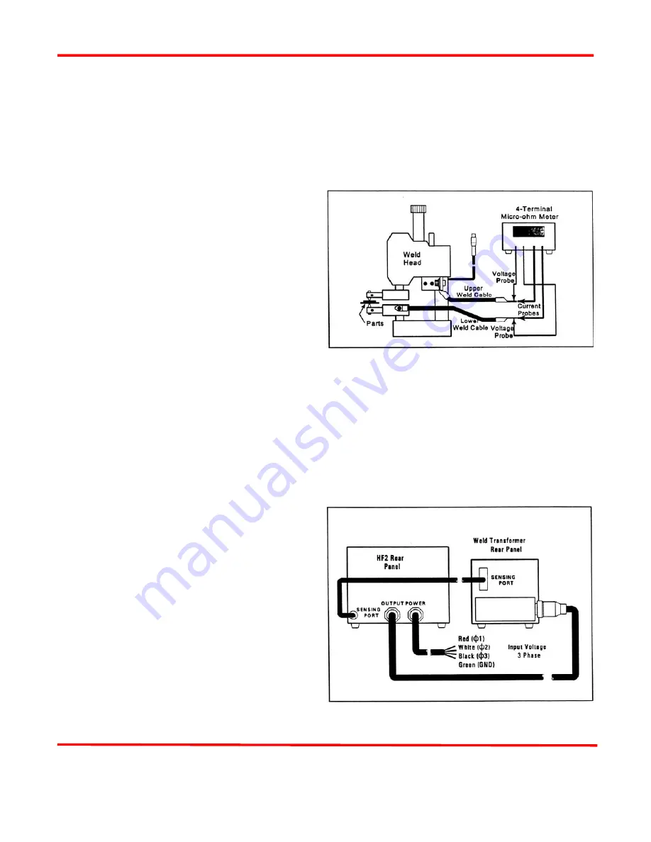
HF2 Maximum Secondary Loop Resistance Measurement (Figure 2-4)
1
Connect a four terminal micro-ohmmeter
as shown in Figure 2-4.
2
Put the parts to be welded between the
electrodes.
3
Measure the total loop resistance which
includes both Weld Cables, Weld Head,
Electrodes, and parts.
4
If the total loop resistance exceeds the
table value, use:
A)
Larger diameter Weld Cables
Figure 2-4. Secondary
Resistance Measurement
B)
Shorter length Weld Cables, or
C)
Copper Bus Bars to connect the HF2 Weld Transformer to the Weld Head. If these
suggestions do not work, then a different Weld Transformer Model may be required.
CAUTION:
For product safety, the system power cable and all inter-unit cabling should be as short as
possible, and be dressed so that all cables stay separated.
HF2 Weld Control to HF2 Weld Transformer Connections (Figure 2-5)
The HF2 Weld Control must always be connected
to the HF2 Weld Transformer as shown in Figure 2-
5, regardless of what Weld Head System is used.
1
Connect the HF2 Weld Control POWER
Cable to the line voltage source as
specified in
Chapter 2, Power Line
Voltage, Current, and Wire Size
Requirements.
2
Connect the HF2 Weld Control OUTPUT
Cable to the matching connector on the
HF2 Weld Transformer.
3
Connect the HF2 Weld Control SENSING
PORT Cable to the matching connector on
the HF2 Weld Transformer.


