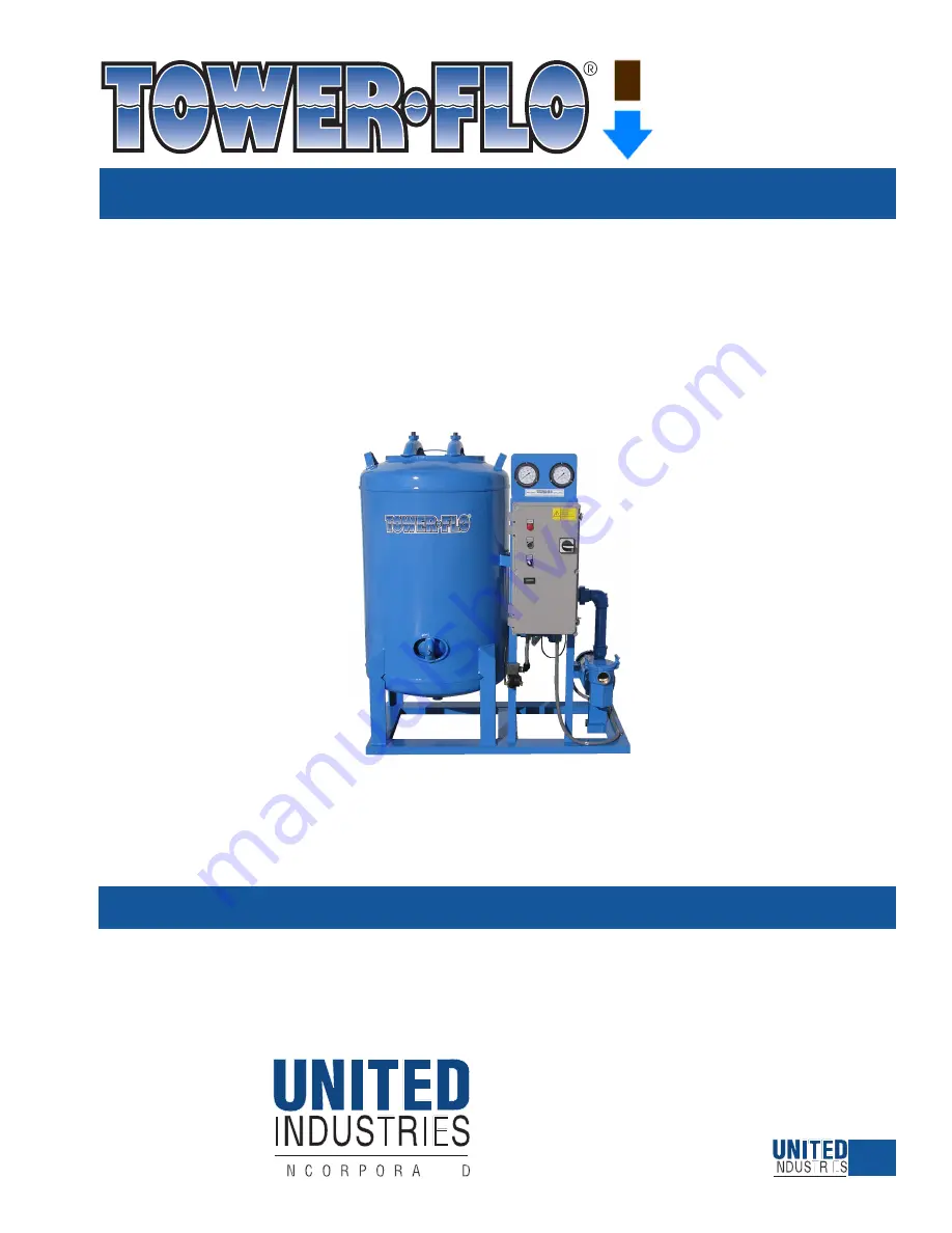
background image

for

Series

TFH

Water Filter Systems

T

OWER-FLO

®

 Division

United Industries, Inc.

P. O. Box 58

Sterling, KS 67579

800-835-3272 • 620-278-3160

Fax 800-500-3115 • 620-278-3115

www.towerflo.com

TECHNICAL MANUAL

Complete information for

Engineering, Installation, Operation & Maintenance

of Tower-Flo

®

 Series TFH Water Filter Systems

1

Summary of Contents for Tower-Flo TFH Series

Page 1: ...nited Industries Inc P O Box 58 Sterling KS 67579 800 835 3272 620 278 3160 Fax 800 500 3115 620 278 3115 www towerflo com TECHNICAL MANUAL Complete information for Engineering Installation Operation Maintenance of Tower Flo Series TFH Water Filter Systems 1 ...

Page 2: ...4 13 Pump Curve TFH 36 13 TFH ELEC 3PH 4 14 Electrical Schematic Three Phase 14 CONDINT 2 17 Conductivity Interface 15 TFH PTS MC 4 13 Parts Major Components 16 TFH PTS SPM 11 07 Parts Strainer Pump Motor TFH 18 24 and 30 17 TFH BW OPS 10 02 Backwash Options 18 TFH FWBW 2 03 Fresh Water Backwash from Municipal Supply Schematic 19 INISS 4 98 Installation Issues 20 SWEEP 4 98 Basin Sweeper Piping 21...

Page 3: ...r improper maintenance 2 Any items manufactured by other companies and used by United Industries in its products may carry warranties by the original manufacturers 3 United Industries is not liable for incidental or consequential damages loss of time inconvenience incidental expenses labor or material charges in connection with removal or replacement of the equipment United Industries is not respo...

Page 4: ...efit you must complete and return the Warranty Registration Card below within 10 days of installation to register your warranty and ensure your warranty rights Failure to complete and return this Warranty Registration Card will result in your warranty being limited to 12 months from the date of factory shipment EXTEND YOUR WARRANTY COMPLETE AND RETURN THIS WARRANTY REGISTRATION CARD WITHIN 10 DAYS...

Page 5: ...atically stop the system s pump whenever valves are to be shifted which prevents water hammer pipe flexing and the risk of damage to col lection laterals in the vessel Standard control panels include five sets of dry contacts for BMS interface 1 alarm on repeat backwash 2 remote pump on off with HOA switch 3 remote indication of common alarm motor trip indica tion 4 remote indication of backwash o...

Page 6: ...gs UL and CSA listed ____ HP and at the follow ing VAC phase and Hz ___________________ ___ Standard TFH 36 TEFC heavy gauge rolled steel case NEMA 145JM frame Class F insulation double shielded prelubricated ball bearings UL and CSA listed ____ HP and at the following VAC phase and Hz ___________________ ___ Option 575V STRAINER ___ Standard TFH 18 24 30 Basket type brass body ABS basket brass co...

Page 7: ...een among ____ units to prevent simultaneous backwash of multiple filter units 0 60 minute adjustable lockout time delay program field connection between among control panels by others ___ Option Contacts for connection to BMS additional specifications required from owner ___ local lights and remote contacts indication of filter or backwash operating mode ___ other be specific ____________________...

Page 8: ... Sch 80 PVC ___ brass for field installation by oth ers on drain piping from tank for isolation and or throttling LIQUID LEVEL ___ Liquid level control assembly for backwash surge tank to interrupt filter pump if when surge tank nears capacity Includes ITT McDonnell Miller 750B liquid level controller mounted in separate NEMA 3R enclo sure requiring separate 120 V power supply factory mounted on f...

Page 9: ...E GAUGE PANEL CONTROL PANEL BALL VALVE BRASS 3 WAY BACKWASH TO WASTE FILTER EFFLUENT FILTER INFLUENT VALVE ACTUATOR WITH LINKAGE DRAIN HANDHOLE PUMP MOTOR VESSEL c C F E G H D b B a A TFH 18 DIMENSIONS Influent Connection 2 FPT Effluent Connection 2 FPT Backwash Connection 2 FPT A Vessel OD 18 a Flange OD 24 B Overall Length 41 b Base Length 38 C Overall Width 25 c Base Width 16 75 D Vessel to Inf...

Page 10: ...VE GAUGE PANEL CONTROL PANEL BALL VALVE BRASS 3 WAY BACKWASH TO WASTE FILTER EFFLUENT FILTER INFLUENT VALVE ACTUATOR WITH LINKAGE DRAIN HANDHOLE PUMP MOTOR VESSEL c C F E G H D b B A DIMENSIONS 24 30 Influent Connection 2 FPT Effluent Connection 2 FPT Backwash Connection 2 FPT A Vessel OD 24 30 B Overall Length 49 55 b Base Length 46 52 C Overall Width 28 34 c Base Width 22 26 D Vessel to Influent...

Page 11: ...IEF VALVE GAUGE PANEL CONTROL PANEL BACKWASH TO WASTE FILTER EFFLUENT FILTER INFLUENT DRAIN HANDHOLE PUMP MOTOR VESSEL c C F E G H D b B A TFH 36 DIMENSIONS Influent Connection 2 5 Flanged Effluent Connection 2 FPT Backwash Connection 2 FPT A Vessel OD 36 B Overall Length 62 b Base Length 58 C Overall Width 40 c Base Width 30 D Vessel to Influent 20 5 E Grade to Influent 11 F Grade to Effluent Val...

Page 12: ... towerflo com Form TFH182430CURVE 2 07 Data presented here is the best available at the time of publicaton United Industries and or its representatives assume no liability for its use Series TFH PERFORMANCE CURVE CAPACITY IN GALLONS PER MINUTE Curve based on 3450 RPM impeller speed 50 cycle units available T F H 3 0 TFH 24 T F H 1 8 ...

Page 13: ...e 3 hp Speed 1800 Frame 182T Standard NEMA Enclosure TEFC Sizing criteria Max Power on Design Curve Selected from catalog Aurora Pumps 60 Vers 4 3 Data Point Flow 141 US gpm Head 44 8 ft Eff 73 Power 2 18 hp NPSHr 4 59 ft Design Curve Shutoff head 50 9 ft Shutoff dP 22 psi Min flow BEP 73 149 US gpm NOL power 2 96 hp 223 US gpm Max Curve Max power 2 96 hp 223 US gpm Curve efficiencies are typical ...

Page 14: ...e no liability for its use RED X1 TFH SERIES FILTERS CONTROL TERMINAL WIRING DIFFERENTIAL PRESSURE SWITCH ACTUATOR I O SWITCH ON POSITION I WHITE WHITE WHITE BLACK 1 5 14 15 X3 X3 X3 16 17 17 NOTES 1 Trip block will be selected in accordance with Table 1 2 Main disconnect and branch circuit protection must be sized in accordance with trip block selected 3 Primary supply taps to transformer will be...

Page 15: ...and filter control panel allows an automatic water chemistry controller to be pro grammed with a low conductivity setpoint below which none of the three filter backwash initiation sources ΔP switch manual pushbutton 100 hour backup timer can cause a backwash a filter backwash cannot inadvertently drive the conductivity too low that low conductivity set point should close a dry contact wired to the...

Page 16: ...15 11 07 to present F000005 Gasket 14 x 18 manway M846396 Top assembly 14x18 manway Hand hole M846181 Gasket hand hole 4x6 M846185 Top assebmly 4x6 hand hole Top assembly Cover yoke bolt and gasket Pressure Gauges 2 required P181045H Gauge pressure 0 100 PSI 3 5 standard gauges P181045L Gauge pressure 0 60 PSI 3 5 P181045T Gauge pressure 0 160 PSI 3 5 Valve Actuator M870330K Valve ball 3 way brass...

Page 17: ...5 P170422 Trap body bronze 5 x 2 1 7 P263171 Plug volute and or trap 2 8 M808698 Bolt trap to volute 4 9 P171915 Pump base 1 10 P171917 Lockwasher 2 Item Part Description Qty 11 P171920 Hex bolt 5 16 18 x 3 4 2 12 P170415 Gasket trap to volute 1 14 P170417 Volute 1 16 P171976 Seal 1 17 P171974 Gasket volute 1 18 P171903 Hex bolt 3 8 16 x 5 8 4 19 P170420 Bracket 1 20 P171902 Hex bolt 5 16 18 x 5 8...

Page 18: ...wash flow requirement of 75 of flow rate Ordering this option changes the facepiping from the standard configuration as shown on pages 9 10 23 to the configuration shown on the following page Municipal water supply is connected to the bottom valve as shown Additionally this option provides a flow control valve factory preset to the maximum flow rate of the vessel to be installed on site in the mun...

Page 19: ...ion is a flow control valve for field installation The end user is respon sible for the addition of a pressure controlling device in the municipal water supply line set to a maximum 30 psi Local code may also require the addition of a back flow preventer in the municipal water supply line Municipal water supply is connected to the top port of the bottom valve The additional equipment required to c...

Page 20: ...s been given to operating pressure of the filter system and flow promotion issues If you as the installer have any questions contact your local Tower Flo Representative or contact the Tower Flo Water Filter Systems Division of United Industries Inc INSTALLATION STYLE BASIN SWEEPER PIPING SYSTEM A basin sweeper piping system will use the return flow of filtered water from the filter system to help ...

Page 21: ...size of suction openings will always be determined by the following the total open area of suction line openings should be equal to or slightly greater than 125 of the total open area of the discharge pipe size 1 5 50 63 19 24 11 14 36 45 16 20 9 12 2 68 85 31 39 18 23 61 77 27 34 16 20 2 5 98 123 44 55 25 32 87 109 39 49 22 28 3 67 84 38 48 60 75 34 43 4 116 145 65 85 104 130 59 74 6 148 185 133 ...

Page 22: ... pipe runs significantly reduce the ability of the pump to prime itself When install ing your filter in a self priming position limit horizontal pipe runs to a maximum of 18 inches If this limit is not practical for your installation we recommend the use of a foot valve in the suction line in order to maintain self priming capability WARNING TOWER FLO Filters should never be installed on a dirty b...

Page 23: ...SH PIPE DEFLECTOR VANE MUST BE PLACED PERPENDICULAR TO THE FLOW OF WATER AND MUST BE IN THE WATER DEFLECTOR VANE STEP 3 PLUMBING A Fabricate and install sweeper piping system in water source with holes sized according to the Sweeper Pipe Sizing tables and formula found on page 10 of this manual or if using TOWER FLO Sweeper Eductor Nozzles follow directions supplied with the nozzles The sweeper pi...

Page 24: ...tacts for remote communication with a building control system BCS 1 control terminals 8 9 are for remote indication of repeat backwash alarm 2 control terminals 10 11 are for remote pump on off in combination with the HOA switch They are factory jumpered so that the system will operate in either Hand or Auto To connect to the BCS remove the jumper across terminals 10 11 and connect BCS wiring STEP...

Page 25: ...washers from the flange Carefully lift or hoist the top head off of the filter vessel while assuring that the gasket is protected from damage C In TFH 18 24 30 filters inspect the underdrain laterals and ensure the slots in the laterals are facing down ward In TFH 36 filters the underdrain laterals are shipped loose for field installation in order to prevent damage to the laterals during shipment ...

Page 26: ...he on position There will be a 2 30 minute time delay before the pump starts this delay will occur any time the system is restarted after a power interrruption or disconnect Allow up to 3 to 4 minutes for pump to prime Pump is primed when strainer remains filled with water If pump does not prime repeat steps D E and F F Check proper pump rotation with arrow on pump housing by turning system on off...

Page 27: ...00 835 3272 620 278 3160 Fax 800 500 3115 620 278 3115 www towerflo com Data presented here is the best available at the time of publicaton United Industries and or its representatives assume no liability for its use Series TFH THIS PAGE INTENTIONALLY BLANK ...

Page 28: ...anent media filter systems have a difference in pressure between fluid entering the filter influent and the fluid exiting the filter effluent This pressure drop commonly referred to as differential pressure or P will be approximately 3 psi when the filter media is clean As system water passes through the media bed particles in the water become trapped in the media As the amount of trapped particle...

Page 29: ...nual backwash push button is pressed or Timer T5 elapses which initiates Timer T1 and Timer T2 Timer T1 energizes the control relay to the valve actuators changing the valves to backwash position Timer T2 interupts the pump motor contactor stopping the pump while the valves rotate 3 Timer T2 elapses pump motor contactor is re energized restarting the pump Filter is now in backwash mode for 3 minut...

Page 30: ...nnection 3 Visually inspect strainer basket through lid If cleaning is necessary turn system off release pressure from filter vessel remove strainer lid clean basket replace basket and lid following recommended safety procedures and restart system following the Start Up Procedure 4 Check pressure gauges for proper operation MONTHLY 1 Place unit in off position 2 Check automatic air release valve f...

Page 31: ...t Sanitize the media bed with bleach Look to see if the surface of the media bed is clean smooth and flat Remove any accumulation of fibrous materi als i e cottonwood tree seeds or heavy materials that are not being removed by backwash action The appear ance of ridges and valleys on the surface of the media bed would indicate the beginning of hard spots down in the media bed under the ridges and a...

Page 32: ...f volute Addition of a good rust inhibitor into liquid end of the pump is recommended to prevent corrosion Be sure the motor is kept dry and cov ered 3 VESSEL VALVES Drain vessel and valves by removing the drain plug in the bottom of the vessel 4 GAUGES DIFFERENTIAL PRESSURE SWITCH Disconnect influent and effluent pressure lines at facepiping and allow to drain then reconnect For YEAR ROUND OPERAT...

Page 33: ...filter bed for foreign material and contaminated due to clogging or caked sand and remove from tank Replace with same volume of clean new silica sand BACKWASHES TOO A Differential pressure switch adjusted A Using bench air check P set at 10 psi If at 10 psi INFREQUENTLY OR too high for backwash initiation or decrease setting by two to three psi NEVER B Differential pressure switch malfunction B Ch...

Reviews: