
WirelessHART Toxic & Combustible Gas Detector
IM_TCD60-01
www.ueonline.com/vanguard
37
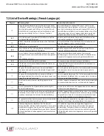
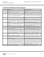
7.3 List of Device Warnings (French Language)
Page(s)
Warning Text
Texte d'avertissement
1,11,20
This device is for monitoring and communicating gas
concentration levels for data collection or record
keeping and does not provide alarm signals.
Cet appareil est destiné à la surveillance et à la com-
munication des niveaux de concentration de gaz pour
la collecte de données ou la tenue de registres. Il n’émet
pas de signal d'alarme.
1,20
Misuse of this device may cause explosion and/or
personal injury. These instructions must be thor-
oughly read and understood prior to installation of
the device.
Une mauvaise utilisation de cet appareil peut provo-
quer une explosion et/ou des blessures. Ces consignes
doivent être lues attentivement et bien comprises avant
l'installation de l’appareil.
1,20
The end-user is responsible for maintaining the
device in full, operational condition.
L'utilisateur final est responsable de l’entretien de
l’appareil afin d’assurer un bon état de fonctionnement
à pleine capacité.
1
To ensure proper ingress protection, the front and
rear covers must be installed, and fully bottomed out
against the base enclosure (i.e. metal-to-metal con-
tact). It is recommended to use a wrench or any tool
across the cover lugs to tighten the covers down.
Pour assurer une protection adéquate, l’avant et
l’arrière couvercles doivent être installés et complète-
ment fondés contre l’enceinte de base (c’est-à-dire
contact métal-métal). il est conseillé de une clé ou un
outil à travers les onglets de protection pour resserrer
les couvercles.
1,9
Exposure to toxic gas may result in loss of conscious-
ness or death. See Annex 1 for toxic gas sensor
details.
Une exposition à ce gaz peut provoquer une perte
de conscience, voire la mort. Voir l’an-nexe 1 pour les
détails du capteur de gaz toxiques.
1,9
Combustible gas accumulation in closed areas may
cause explosion, and result in loss of consciousness
or death. See Annex 1 for combustible gas sensor
details.
L’accumulation de gaz combustible dans les zones fer-
mées peut provoquer une explosion, et entraîner une
perte de conscience ou la mort. Voir l’annexe 1 pour les
détails du capteur de gaz combustible.
1
Avoid dropping the device as loosening of the threaded
flame-proof joints or permanent damage may occur.
Éviter de faire tomber l’appareil. Ceci pourrait desserrer
les joints filetés ignifuges ou endommager l’appareil de
façon permanente.
1
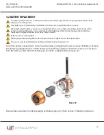
New sensors must be calibrated after installation (see
Section 3.2).
Les nouveaux capteurs doivent être étalonnés après
l'installation (voir Section 3.2).
1
When not in use, the device should be stored in a
clean, dry area and within the temperature range
listed within the device’s environmental specifica-
tions.
Lorsqu'il n’est pas utilisé, l’appareil doit être stocké dans
un endroit propre et sec et à une plage de tempéra-
tures donnée dans les spécifications environnementa-
les de l'appareil.
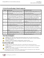
3
Device is shipped without the sensor or battery
installed. Both must be installed prior to use. See
Section 2.0 Installation for further information.
L'appareil est livré sans que le capteur ni la batterie ne
soient installés. Les deux doivent être installés avant
utilisation. Voir la Section 2.0 « Installation » pour de
plus amples informations.
4,9,11
This device is suitable for Class I, Divisions 1 & 2,
Groups C and D; or non-hazardous locations only. -40
°C (-40°F) ≤ Tamb. ≤ 65°C (149°F). Enclosure Type 4X
and IP66 excludes sensors.
Cet appareil est uniquement adapté à une utilisation
dans les lieux de Classe I, Divisions 1 et 2, de Groupes C
et D ou non-dangereux. - 40 °C (-40°F) ≤ T amb. ≤ 65°C
(149°F). Boîtier de type 4X et IP66 le capteur est exclut.
4,9,11
This device is ATEX and IECEx certified for equip-
ment category 2. Suitable for appropriate use in gas
zone 1.
Cet appareil est certifié ATEX et IECEx pour les équipe-
ments de catégorie 2. Convient à une utilisation appro-
priée dans une zone classée 1 (gaz).


