IMT120 15
4
Type 820E
To adjust the switch:
❶
Remove the set point adjustment knob and clear cover
from the indicating enclosure (square) to access the pointer
mechanism for adjustment.
❷
Connect test lights or listen for the individual switch clicks
to indicate switch operation.
❸
Move the set point adjustment pointer (red) up the scale
past the indicating pointer (black). This permits checking the
set point by moving the actuating lever upward with a finger,
or tool, simulating thermal assembly movement. Note switch
operation on the test lights.
❹
Loosen adjustment pointer mounting screw “A” and move the
adjustment pointer (red) until it aligns with the indicating pointer
(black) (see Figure 5). When the switch clicks re-tighten the screw.
Type 822E
NOTE:
Type 822E has a single set point adjustment-
knob and adjustment pointer (red) for both switches.
Both switches are standardly factory set together
within 5% of the adjustable set point range. Turning
the set point adjustment knob adjusts both switches
simultaneously, maintaining a fixed separation
between them. To adjust the switches:
❶
Remove the explosion-proof enclosure cover to access the
switches for adjustment.
❷
Remove the set point adjustment knob and clear cover
from the indicating enclosure (square) to access the pointer
mechanism for adjustment.
❸
Connect test lights or listen for the individual switch clicks
to indicate switch operation.
❹
Move the adjustment pointer (red) up the scale past the
indicating pointer (black), actuating both switches, by moving
the actuating lever upward with a finger, or a tool, simulating
thermal assembly movement (see Figure 5). Note switch
operation on the test lights.
❺
The set point of switch #1 is determined by the adjustment
pointer (red). The set point of switch #2 may be adjusted by
up to 25% of the range span below the switch #1 set point
by turning adjustment “D” with a 5/16” open end wrench
(clockwise) to lower the set point. See page 6 for 822E dual
switch adjustment. The set point of switch #2 should never be
set above that of switch #1.
❻
To align the switch #1 adjustment pointer (red) with the
indicating pointer (black), loosen the adjustment pointer mounting
screw “A” and align the adjustment pointer (red) with the indicating
pointer (black), then re-tighten screw “A” (see Figure 5).
NOTE: Indicating Pointer Deflection (820E, 822E)
The indicating pointers will read slightly low when
the bulb temperature is 15° F above the controller
setting. This deflection is normal and repeatable
(approximately 0.5% of scale range on single switch
models) and is due to the transference of the switching
mechanism load to the thermal system. It can be
measured by moving the setting pointer from the high
to the low end of the scale and observing the resultant
indicating pointer deflection.
NOTE:
To adjust the Indicating Pointer (820E, 822E):
❶
Use an accurate test thermometer such as a thermocouple
with its probe mounted directly to the center of the sensing bulb.
❷
Before making any adjustments, allow process temperature
to stabilize; i.e., successive on-off cycles repeated.
❸
Correct any difference between the indicating pointer
(black) and the test thermometer by holding the compensator
with a 5/16” wrench while turning the zero adjustment “C” on
the thermal assembly with a second 5/16” wrench (see Figure
5) until the indicating pointer (black) reads the same value
as the test thermometer. Turning the zero adjustment “C”
clockwise lowers indicated reading.
❹
Compare the process temperature with the set point
adjustment pointer (red).
❺
Loosen the adjustment pointer mounting screw “A” to align
set point adjustment pointer (red) with the indicating pointer
(black), then re-tighten screw “A”.
Correction of Capillary (820E, 822E)
If the length of capillary immersed in the process
differs from the amount immersed (6”, see Mount
-
ing Bulb & Capillary in Part I - Installation) at the
factory calibration bath, a calibration shift will
occur.
The error may be corrected as follows:
❶
Move pointer to the highest temperature setting. Note
indicating scale reading with the head and sensor at room
temperature.
❷
Loosen the two thermal assembly mounting screws.
❸
Re-position the housing index against the calibration on
the instrument case (or skeleton casting) at a rate of 1 division
line per capillary length listed in Figure 6. Move to the left
if capillary is to be added to the process, or to the right if
capillary is to be removed from process.
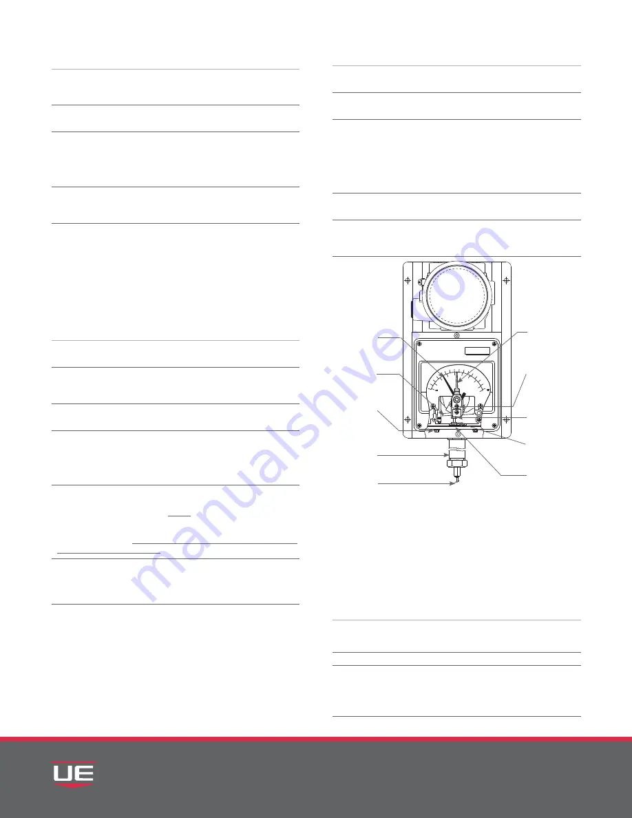
Figure 5: Indicating
Enclosure Internals
CAPILLARY
INDICATING
POINTER
(BLACK)
THERMAL
ASSEMBLY
MOUNTING
SCREWS (2)
THERMAL
ASSEMBLY
HOUSING
INDEX
ADJUSTMENT
POINTER (RED)
ADJUSTMENT
POINTER
MOUNTING
SCREW
(ADJUSTMENT “A”)
ZERO
ADJUSTMENT
“C” 5/16 HEX
COMPENSATOR
ACTIVATING
LEVER


