background image

14

Copyright 2007 unitech Electronics Co., Ltd. All rights reserved. unitech is a registered trademark of unitech Electronics Co., Ltd.

RF Communication

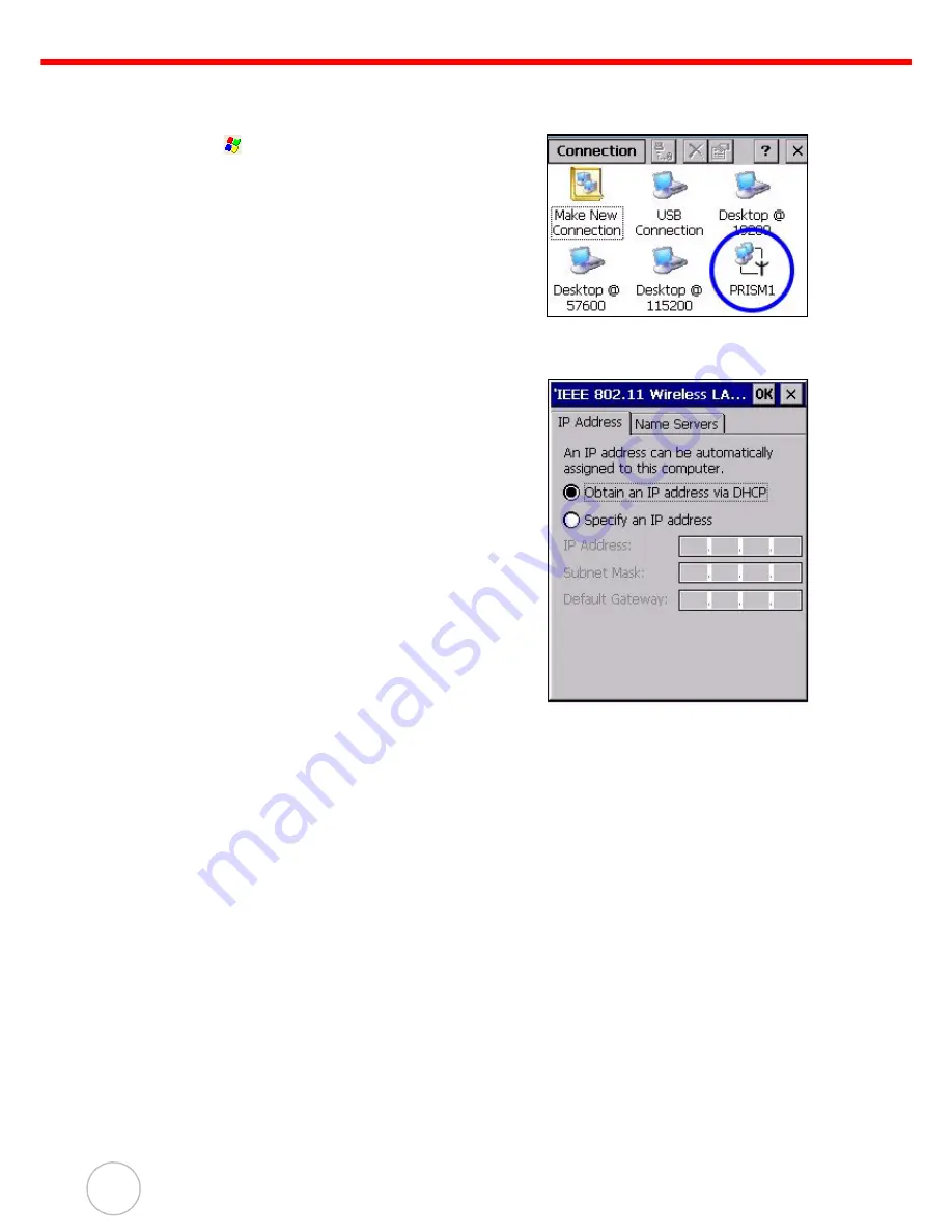
With Windows CE support of the TCP/IP protocol, users can use the MR650 to link to the Internet.

1.

Tap  

 Settings 

 Network and Dial-Up Connec-

tions.

2.

Double-tap PRISM1 to set up the IP to connect to 
Internet.

NOTE:

Contact your system administrator for the 
IP settings for this dialog window.

Summary of Contents for MR650

Page 1: ...unitech MR650 Video TAS Terminal User s Manual E ESC F4 F3 F2 F1 unitech unitech 400513G Rev C...

Page 2: ......

Page 3: ...his manual may be trademarks or registered trademarks of their respective companies and are hereby acknowledged Regulatory Compliance Statements FCC Statement This is a FCC Part 15 Class A product In...

Page 4: ...a slightly cooler environment It is essential that batteries are charged within the stated range of 5 C to 50 C Charging batteries outside of the specified range could damage the batteries and shorten...

Page 5: ...3 Setting up the MR650 4 Opening the Back plate 4 Connecting Power 5 Charging the Battery 5 Turning the MR650 on for the First Time 6 Powering On 6 Calibrating the MR650 Screen 6 Setting the Date and...

Page 6: ...ess 19 WiFi Connection 20 Chapter 4 Barcode Scanner Programs 22 Scanner Settings 22 Scan2Key 22 Registry Backup Restore 23 Audio Demo Program 24 Softkeys 25 Chapter 5 Power System 26 Charging the Back...

Page 7: ...om security and provides cost efficient solution for TAS applications Features Powerful system Microsoft Windows CE 5 0 Professional Plus operating system Intel PXA270 processor with speeds up to 520M...

Page 8: ...The MR650 screen ships with a protective plastic film You may remove it if desired by peeling from one corner The screen will be more susceptible to scratching without the film but will be more reada...

Page 9: ...tech unitech unitech E ESC F4 F3 F2 F1 unitech unitech E ESC F4 F3 F2 F1 Speaker Microphone 1 3 Megapixel CMOS Camera 6 Key Keypad Proximity Reader Finger Print 5 6 inch Color Touch Panel Proximity Re...

Page 10: ...ing the Back plate Follow these instructions to open the back plate for accessing the MR650 s internal components 1 Insert the key provided into the security lock and then turn the key counterclockwis...

Page 11: ...ter may not be properly stored until the built in backup battery has been adequately recharged 1 Plug the 12V DC connector into the terminal block 1 2 Plug the adapter into a power socket 2 3 Switch o...

Page 12: ...with the stylus When you have completed the series of taps press the E key to confirm calibration or press the ESC key to cancel it After confirming calibration the Date Time Properties screen appear...

Page 13: ...The following table describes the keys Key Main Function Clock in F1 Function Key Break out F2 Function Key Break in F3 Function Key Clock out F4 Function Key ESC Performs the same function as tapping...

Page 14: ...Keyboard Entering Characters Character input is the same as on a standard PC keyboard Tap the on screen button correspond ing to the character you want to input International Character Support Tap the...

Page 15: ...ctively NOTE Reading software must be enabled in order to operate the scanner This can be a user loaded application or a pre loaded utility such as Scanner Setting Testing Reader Data The MR650 has a...

Page 16: ...of less than 2 seconds The Finger Print Reader comes with 4000 templates Testing Finger Print Verification The MR650 has a built in BIO ID Manager program that enables the user to test finger print ve...

Page 17: ...tap OK The following message appears After placing the finger on the sensor a stamp with the quality percentage and ID number is entered into the program record Verifying the Finger Print Stamp To ve...

Page 18: ...uously Functions as an audio video intercom Additionally facial recognition can be incorporated using third party software The MR650 has a demo program that enables users to capture a still picture wi...

Page 19: ...Cable 1 Plug the provided RS232 communication cable into the PC s 9 pin COM port 2 Connect the other end to the MR650 RS232 interface Port Ethernet Cable 1 Plug an Ethernet cable into the PC s RJ 45 E...

Page 20: ...ronics Co Ltd RF Communication With Windows CE support of the TCP IP protocol users can use the MR650 to link to the Internet 1 Tap Settings Network and Dial Up Connec tions 2 Double tap PRISM1 to set...

Page 21: ...e MR650 terminal The MR650 terminal ships with ActiveSync already installed You can download and install the most current version of ActiveSync from www microsoft com Installing Microsoft ActiveSync I...

Page 22: ...esn t start automatically click Pro grams Microsoft Active Sync If a message appears indicat ing that it is unable to detect a connection click the Cancel button and manually configure the communicati...

Page 23: ...Chapter 3 Data Communication 17 8 Check Enable direct connections to the desktop computer Tap Change Connection 9 Select the type of connection you want to use 10 Tap Programs Communications PC Link...

Page 24: ...use one of the following two ways to set the IP address Obtaining an IP Address via DHCP Server Specifying an IP Address Obtaining an IP Address via DHCP Server To obtain the IP address via DHCP serve...

Page 25: ...nel and then double tap Network and Dial up Connections 2 Tap PRISM1 3 Tap the radio button next to Specify IP Address 4 Input the proper IP address Subnet Mask and Default Gateway 5 Tap the Name Serv...

Page 26: ...uilt in RF facility This chapter guides the user on how to setup the RF setting 1 Double tap the Summit Client Utility 2 Under Main tab for Active Profile select ThirdPartyConfig 3 A Power Cycle is re...

Page 27: ...e RF card is detected you will see the RF setting window pop up 7 Tap Add New Or double tap your preferred network to add a new SSID 8 Enter the SSID Uncheck The key is provided automatically Enter th...

Page 28: ...scanned data and save the settings Tap Settings Control Panel Scanner Settings to display the Scanner Control Panel Scan2Key The Scan2Key application routes input from a scanner port to a keypad buff...

Page 29: ...malfunctions or settings are lost the user can go to Registry Restore to retrieve the settings To use Registry Backup 1 Tap Programs Utilities RegBackup 2 Tap Save to save the current registry settin...

Page 30: ...ut playback 1 Double tap the My Device icon on the Windows CE desktop 2 Double tap the Windows folder 3 Double tap wavtest to open the program The testing program is displayed 4 Do one of the followin...

Page 31: ...Chapter 3 Barcode Scanner Programs 25 Softkeys Softkeys is a numeric onscreen keypad utility to input numeric keys 1 Tap Programs Utilities Softkeys 2 The Softkeys program appears...

Page 32: ...ed from exter nal power the unit will enter sleep mode and turn off the backlight When you tap the touch panel the backlight is set to minimum brightness to saving battery power Checking the Battery S...

Page 33: ...nge the automatic power settings 1 Open the Power Properties by tapping Settings Control Panel Power 2 Tap the Schemes tab 3 Tap the automatic shut off time arrow to select from a list of time periods...

Page 34: ...rnal Power Adjust the screen brightness by tapping Settings Control Panel Backlight Set the backlight behavior and drag the On Intensity and Dim Intensity sliders to the desired levels Field Descripti...

Page 35: ...default factory settings However data and application programs stored in the Flash Storage will be not be deleted Never perform a cold boot unless a warm boot does not correct your problem When you p...

Page 36: ...hone input Expansion Slot CF type II card slot for wireless 802 11 b g SD slot for memory expansion Power Source Main Lithium lon 3 8V 4000mAh main battery pack Backup One rechargeable Li ion backup b...

Page 37: ...NC NO RY 2 RY 2 C NC NO RY 3 RY 3 1 3 5 7 9 11 13 15 17 19 21 23 2 4 6 8 10 12 14 16 18 20 22 24 RL1 CTRL RL3 CTRL BAT 3P3V DIGIT INPUT1 DIGIT INPUT3 AV 5 GND TGND TGND SUPVCC5 SUPVCC5 SUPVCC5 RL2 CTR...

Page 38: ...o In Cathode 9 DI4 L Photo In Anode 10 DI4 H Photo In Cathode Pin Name Description 1 DC In 12V 2A 2 GND GND 3 RY1 C Common 4 RY1 NC Normal Close 5 RY1 NO Normal Open 6 RY2 C Common 7 RY2 NC Normal Clo...

Page 39: ...to get the quick response We have six regional services center and choose your region to get our quick sup port and their contact information can be found in our websites provided as below UTC China...

Reviews: