background image

Copyright 2008 Unitech Electronics Co., Ltd. All rights reserved. Unitech is a registered trademark of Unitech Electronics Co., Ltd.

46

Copyright 2008 Unitech Electronics Co., Ltd. All rights reserved. Unitech is a registered trademark of Unitech Electronics Co., Ltd.

47

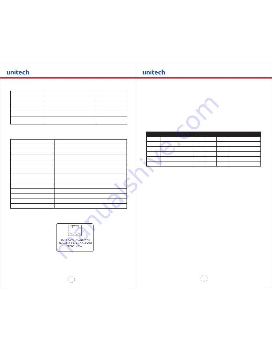
RJ25 CONNECTOR PIN # FUNCTIONAL DESCRIPTION

SIGNAL NAME

3

RS232 from Host  (INPUT)

RXD

2

RS232 from Printer (OUTPUT)

TXD

6

Request to send from Host (INPUT)

RTS

4

Clear to send from Printer(OUTPUT)

CTS

1

5

Logic common

COM


Table C.1 – Serial Interfaces Signals and pinouts

C.1.4 RS232C TECHNICAL SPECIFICATIONS

Technical Specification Name

Technical Specification Value

Data Transfer Rate 

2400 – 38.4K Baud

Word Length 

10 or 11 bits

Start Bit

1

Data Bits

 8

Parity Bit

None, Odd or Even

Stop Bits

Auto Select 1 or 2

Signal Levels 

RS232C

Mark or Logical 1 

-3 to -15 VDC

Space or Logical 0 

+ 3 to + 15 VDC

Handshaking

Two modes are supported(Software and Hardware)

Hardware

RTS/CTS

Software

XON/XOFF

Auto Power Up

Positive Signal on RTS input turns printer on


Table C.2. – RS232C – Technical Specifications

Figure 2.0  

RJ-25 Data Connector


C.2.0 Infrared Communications (IrDA)

In IrDA mode the printer can be powered up by pressing the power <On/Off> switch. 

If no IrDA connection is made, the printer will automatically power down to a lower 

power level to conserve battery life. It will remain in a “sleep” mode until an IrDA 

connection is made, at which time the printer will “wake” up and print the requested 

data .Pressing the power switch again will turn the printer <OFF>. The printer can be 

either in Set  IrDA mode which is fixed at 9600 bps baud rate or in Variable IrDA mode 

where the baud rate is negotiated between the printer and the host device and can go 

up to 38400 baud rate. It can also be in Direct IrDA mode which is described in detail 

below. The following table shows the required printer settings for IrDA mode. 


Switch #

Function

Switch


Switch


Switch


NOTES:

1 & 5

Communication Interface

SW1

SW5

SW7

RS232

Off

Off

SET SW 2,3,6 &7

RS232 and Bluetooth

Off

On

Defaults to 38.4k Baud

IrDA Set to 9600

On

Off

Baud rate fixed  to 9600 

IrDA Variable 9600-38.4K On

On

Direct IR

On

Off

On

Defaults to 9600  Baud


Table C.3 – IrDA Mode 

2.1 Direct IR

The Unitech MP200 printer also supports direct IrDA. When in that mode the printer 

surpasses the IrDA stack. This mode is intended for host devices that only support the 

physical layer of the IrDA communication. For the printer to be in direct IrDA mode you 

need to have Dip Switch # 1 and Dip Switch # 7 in the ON position.

C.3.0 Bluetooth Communications (Option):

The MP200 Printer Supports a Bluetooth Option. The printer control card 

communicates with the Bluetooth™ base band interface at 38.4K Baud/sec using no 

parity. To select the Bluetooth™ interface Dip Switch # 5 has to be ON and all other 

Dip Switches have to be OFF.  To have continuous power on set DIP Switch 4 in ON 

position. Refer to table C.0 for detailed explanation of the Dip Switch Settings.        

To gain access to the dip switch, open the paper door and remove the paper roll. The 

dip switch is located at the middle of the paper roll slot. Refer to the User’s Guide for 

the proper location of the referenced dip switch settings 

!

Summary of Contents for MP200

Page 1: ...MP200 Mobile Printer Developer s Manual Rev A Copyright 2008 Unitech Electronics Co Ltd All rights reserved Unitech is a registered trademark of Unitech Electronics Co Ltd...

Page 2: ...ical related issues Should an equipment problem occur please contact the Unitech regional service representatives nearest you For complete contact information please visit the Web sites listed below U...

Page 3: ...er Control Command 22 5 3 Printer Battery Voltage Monitor Commands 22 5 4 Auto Power Down Command 23 5 5 Printer Operating Mode Commands 23 5 6 Supervisory commands 24 Chapter 6 0 Label and Form Print...

Page 4: ...ve previous character in print buffer HT I 0x09 09 Horizontal Tab Tab to 5 9 13 17 21 25 29 33 37 or to the beginning of next line LF J 0x0A 10 Line Feed Advance to beginning of next line VT K 0x0B 11...

Page 5: ...l 2 0 Unitech MP200 Printer Font Control Four commands are defined with the Unitech MP200 printer which allow the user to select different typefaces change the character height width as well as add em...

Page 6: ...ith the three character commands from the table below Command String Action Taken Esc U 1 Enable emphasized print starting with the current text line Esc U 0 Disable emphasized print starting with the...

Page 7: ...each to be received Valid Graphic character sets are from 0x00 to 0xFF Hex using bits 0 7 Esc J n Performs n 0 125mm feed Esc V 0x01 0x00 48 bytes of data This code prints a single line of graphic Ta...

Page 8: ...Graphic Logo none Esc L G OxFF Stop Loading Graphic Logo D X Esc L g n Print Graphic Logo Printer Prints Logo n Table 3 3 Graphic Logo Commands Chapter 4 0 Bar Codes 4 0 Bar Codes The Unitech MP200 pr...

Page 9: ...IRS 0x030 through 0x039 ASCII 48 57 PAIRS 0x030 through 0x039 ASCII 48 57 Table 4 2 Code 128 Start Character Code 128 Data Bytes DATA The data bytes are defined by which character set is defined The p...

Page 10: ...tered Example Command String Printer Output Esc Z 3 0x0A 0x50 1234567890 Prints interleaved 2 of 5 12345678 10 mm high Table 4 4 Interleaved 2 of 5 Example 4 4 UPC EAN JAN specifications Description E...

Page 11: ...er 5 0 Print Contrast Control 5 0 Print Contrast Control The contrast of the printed text or graphics depends on the type of the thermal paper used the printer battery voltage and the printer contrast...

Page 12: ...ds The battery voltage level may be printed or polled by the host device application using the ESC P or CTRL V command strings respectively Command String Printer Response Esc P Prints Battery Voltage...

Page 13: ...s Esc 4 ASCII characters CR LF Firmware Version Query ESC P Firmware Version Esc 4 ASCII characters CR LF Example v 100 Esc 1 0 0 CR LF Hardware Model Query ESC P Hardware model ESC 4 ASCII characters...

Page 14: ...ng the black mark n1 holds the high four bits 0x30 4 high bits n2 holds the low four bits 0x30 4 low bits n1 and n2 can have values 0x30 through 0x3f Table 6 0 Black Mark Printer Commands Chapter 7 0...

Page 15: ...t make a difference it is used only for compatibility with the other models The ASCII and extended tables are located right one after another in each bank The bank numbering starts from location 8000...

Page 16: ...International and PC Line Graphic Font 08x23h Graphic 08w x 23h Command String to Select esc F1 esc k4 or esc k5 File Name TB A 08 DW2 TBXn0823 DW1 A 08 DW2 TBXi0823 DW1 PC Line esc F2 esc k4 or esc...

Page 17: ...s replaced with user designed character A STEP 1 Describe the Bitmap This is best done within a font editing program Characters must be right justified within the 16 x 23 bit cell To ensure the charac...

Page 18: ...operation of the printer remove the battery cartridge from the printer for several seconds Replace the battery cartridge and the new fonts will be ready for use To ensure optimal operation of the pri...

Page 19: ...e use the MP200 driver Use Wordpad or any Windows application to prepare your logo document From printer Setup of Wordpad application Set the paper margins to 0 12 Print your logo document to a file n...

Page 20: ...s indicates that file transmission and storage is completed 7 Cycle power 8 To test the LOGO prn file issue print commands Esc L g n Chapter 8 0 Appendix B Three Track Magnetic Card Reader Option A th...

Page 21: ...the MC reader timer Table B 2 Magnetic Card Read Command Strings Details B 3 0 Magnetic Card Data Output Format The track data retrieved from a magnetic card is transmitted to the host in ISO7811 ASCI...

Page 22: ...s on the GREEN READY LED Once the operator swipes the magnetic card the printer transmits in ASCII format the tracks information found on the magnetic card A good read automatically turns off the MC r...

Page 23: ...mputer A minimum of two connections is required for operation RXD pin 3 and Common pin 1 The proper baud rate and protocol settings are required to communicate with the host device The printer default...

Page 24: ...ll turn the printer OFF The printer can be either in Set IrDA mode which is fixed at 9600 bps baud rate or in Variable IrDA mode where the baud rate is negotiated between the printer and the host devi...

Page 25: ...pressing the ON switch Operation in this fashion will greatly extend the life of the battery cartridge C 3 3 EXTENDED CONTINUOUS ON mode If it is desired to leave the printer on for extended operation...

Page 26: ...aracters printed as received 5 5 ESC P Select Buffer mode characters are printed on D 5 5 ESC V n1 n2 data 8 bit Graphic command 3 1 ESC v n1 n2 data 8 bit Compressed Graphic Command 3 2 Table QR4 Pri...

Reviews: