


035-20646-001 Rev. A (1004)
Unitary Products Group
7
SECTION III: FILTERS
FILTER INSTALLATION
All applications require the use of a filter. A high velocity filter and a side
return filter rack are provided for field installation on GM9 and GY9
models. GF9 models must have a field-supplied filter and mounting
hardware. A field supplied side return filter rack and filter are available
through Source 1 using 1 SF0101. Replacement filter size is shown in
Table 4.
Downflow Filters
A top return filter rack is supplied with the furnace. Two standard filters
are supplied with some units. Downflow furnaces typically are installed
with the filters located above the furnace, extending into the return air
plenum or duct. Any branch duct (rectangular or round duct) attached to
the plenum must attach to the vertical plenum above the filter height.
Refer to Figure 4 for proper installation.
Filters(s) may be located in the duct system external to the furnace
using an external duct filter box attached to the furnace plenum or at the
end of the duct in a return filter grille(s). The use of straps and / or sup-
ports is required to support the weight of the external filter box. Refer to
Figure 5.
If the accessory electronic air cleaner is installed, be sure the air
cleaner is designed to accommodate the furnace CFM (cm/m) and the
air cleaner is installed so it does not obstruct the return airflow. Consid-
eration should be given when locating the air cleaner for maintenance
and temperatures should the indoor fan motor fail to operate. The use
of straps and / or supports is required to support the weight of the elec-
tronic air cleaner. It is recommended that the air cleaner not be located
within 12 inches (30.5 cm) from the top of the return air opening on the
furnace. Refer to the instructions supplied with the electronic air
cleaner.
If pleated media air filters or any filter that has a large pressure drop is
installed in the return air duct system be sure that the pressure drop
caused by the air filter will not prevent the furnace from operating within
the rise range specified on the rating plate. If the furnace does not oper-
ate within the specified rise range then a larger air filter or an air filter
that has a lower pressure drop must be installed. Refer to Figures 4, 5
and furnace accessories for accessory external filter kit options.
IMPORTANT:
For easier filter access in a downflow configuration, a
removable access panel is recommended in the vertical run of the
return air plenum immediately above the furnace.
Accessory External Filter Installation
1.
Install the return filter rack on the top of the furnace return air
opening. Secure the filter rack to the front and back flanges with
screws. The return air plenum can be placed over the filter rack
and the branch ducts (rectangular ducts and / or round ducts) can
be attached to the plenum. Route the combustion air and the vent
PVC pipes around the access panels for the filters.
2.
Install the filter(s) provided or you may install Permanent washable
filters. Filter should extend through the entire length of the filter
rack to prevent air from bypassing the filter. Make sure that any air
filter that is installed in the furnace does not cause an excessive
amount of pressure drop. Refer to Table 16 for air filter perfor-
mance and pressure drops.
IMPORTANT:
Air velocity through throwaway type filters must not
exceed 300 feet per minute (1.52 m/m). All velocities over this require
the use of high velocity filters. Refer to Table 16.
HORIZONTAL APPLICATION
Horizontal Filters
All filters and mounting provision must be field supplied. Filters(s) may
be located in the duct system external to the furnace or in a return filter
grille(s). Filters(s) may be located in the duct system using an external
duct filter box attached to the furnace plenum. Filters must be a mini-
mum distance of 18” (45.8 cm) from the furnace. Any branch duct (rect-
angular or round duct) attached to the plenum must attach to the
vertical plenum above the filter height. The use of straps and / or sup-
ports is required to support the weight of the external filter box.
An accessory filter rack is available. Refer to Figure 4 and the instruc-
tions supplied with the furnace accessory external filter kit options.
TABLE 4:
Filter Sizes
Input / Output
BTU/H (kW)
CFM
(m
3
/min)
Cabinet
Size
Top Return
Filter in (cm)
60/55 (17.57/16.10)
1200 (34)
B
(2) 14 x 20 (36 x 51)
80/75 (23.42/21.96)
1200 (34)
B
(2) 14 x 20 (36 x 51)
80/75 (23.42/21.96)
1600 (45)
C
(2) 14 x 20 (36 x 51)
100/95 (29.28/27.82)
1600 (45)
C
(2) 14 x 20 (36 x 51)
100/95 (29.28/27.82)
2000 (57)
C
(2) 20 x 20 (51 x 51)
120/112 (35.14/32.80)
2000 (57)
D
(2) 20 x 20 (51 x 51)
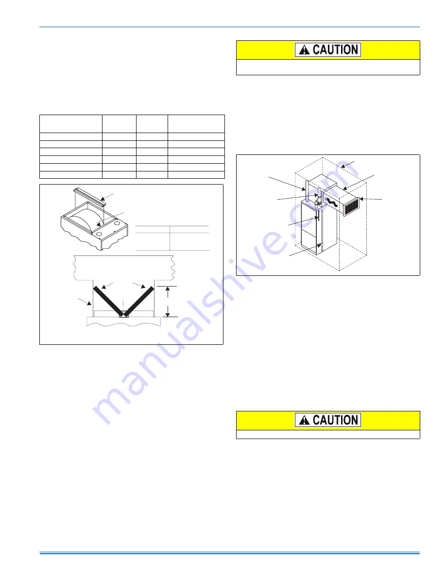
FIGURE 4:
Accessory Downflow Filter Rack
FILTER RACK
(factory supplied with some furnaces)
RACK AND FILTERS SECURED
INSIDE BLOWER SECTION
FOR SHIPMENT
DUCTWORK
FILTERS
BRANCH
DUCTS
FH
CROSS SECTION A-A
(with Plenum and filters)
FILTER
RACK
NOTE: FILTER ACCESS THROUGH
DUCTWORK MUST BE PROVIDED
FOR REMOVAL AND CLEANING
CASING SIZE DIMENSION FH
16-1/4”
22-1/4”
26-1/4”
12-3/4”
11”
8-1/4”
All loose accessories shipped with the furnace must be removed
from the blower compartment, prior to installation.
FIGURE 5:
Return Filter Grill and Return Duct Installation
All installations must have a filter installed.
COMBUSTION
AIR
VENT
PIPE
ELECTRICAL
SUPPLY
GAS SUPPLY
(EITHER SIDE)
CLOSET
RETURN
AIR
AIR
FILTERS