background image

035-16626-000-E-0103

Unitary Products Group

15

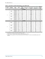
TABLE 9: ELECTRICAL RATINGS INDOOR UNIT - HEAT PUMP ONLY

Blower Motor

HP

Nominal

Heater KW

Power

Supply

Heater

FLA

Minimum

Circuit

Ampacity

Maximum Fuse

Size

1

Minimum Wire

Size AWG

2

Maximum Wire

Length feet

3

Minimum

Disconnect

Amps

F1EH180A33

3

10 KW

208-3-60

20.8

35.5

40

8 AWG

140

60

230-3-60

23.1

38.1

40

8 AWG

133

60

460-3-60

11.5

19.0

20

14 AWG

132

30

20 KW

208-3-60

41.6

61.5

70

6 AWG

222

60

230-3-60

46.2

66.9

70

4 AWG

337

100

460-3-60

23.1

33.5

35

10 AWG

335

60

30 KW

208-3-60

62.5

87.6

90

3 AWG

446

100

230-3-60

69.3

95.8

100

3 AWG

423

100

460-3-60

34.6

47.8

50

8 AWG

533

60

50 KW

208-3-60

104.4

140.0

150

0 AWG

895

150

230-3-60

115.2

153.2

175

2/0 AWG

1073

150

460-3-60

57.6

76.6

80

4 AWG

1347

100

F1EH240A

5

20 KW

208-3-60

41.6

68.0

70

4 AWG

186

100

230-3-60

46.2

70.6

80

4 AWG

251

100

460-3-60

23.1

35.3

40

8 AWG

381

60

30 KW

208-3-60

62.5

94.1

100

3 AWG

233

100

230-3-60

69.3

99.4

100

3 AWG

315

100

460-3-60

34.6

49.7

50

8 AWG

381

60

40 KW

208-3-60

83.3

120.1

125

1 AWG

371

150

230-3-60

92.1

127.9

150

1 AWG

501

150

460-3-60

46.1

64.0

70

6 AWG

604

100

50 KW

208-3-60

104.4

146.5

150

0 AWG

469

150

230-3-60

115.2

156.8

175

2/0 AWG

798

150

460-3-60

57.6

78.4

80

4 AWG

962

100

1.

Maximum fuse or maximum circuit breaker (HACR type per NEC).

2.

Based on three, 75 C insulated copper conductors in conduit and ambient of 30 C.

3.

Based on a 5% voltage drop, since unit controls are powered off the unit supply. Two minute time delay between system 1 and
system 2.

Summary of Contents for FEH180

Page 1: ...G Notes are intended to clarify or make the installation easier Cautions are given to prevent equipment damage Warnings are given to alert installer that personal injury and or equipment dam age may result if installation procedure is not handled properly INSTALLATION MANUAL CAUTION READ ALL SAFETY GUIDES BEFORE YOU BEGIN TO INSTALL YOUR UNIT SAVE THIS MANUAL SPLIT SYSTEM HEAT PUMPS INDOOR UNITS M...

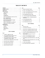
Page 2: ...E FEH180 9 7 RETURN AIR GRILLE FEH240 9 8 BASE ACCESSORY FEH180 10 Fig Pg 9 BASE ACCESSORY FEH240 10 10 SUPPLY AIR PLENUM FEH 180 10 11 SUPPLY AIR PLENUM KNOCKOUTS FEH180 10 12 SUPPLY AIR PLENUM FEH240 10 13 RECOMMENDED DRAIN PIPING 12 14 TYPICAL MOTOR MOUNTING ASSEMBLY 13 15 HOLE LOCATIONS FOR PRESSURE DROP READINGS 13 16 CFM VS PRESSURE DROP 13 17 UNIT DIMENSIONS FEH180 18 18 UNIT DIMENSIONS FEH...

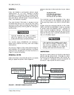
Page 3: ...of the matching outdoor unit refer to PN 035 16192 001 Installer should pay particular attention to the words NOTE CAUTION and WARNING Notes are intended to clarify or make the installation easier Cautions are given to prevent equipment damage Warnings are given to alert the installer that personal injury and or equipment damage may result if the installation proce dure is not handled properly INS...

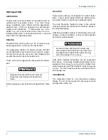
Page 4: ...ION These indoor units are not designed for outdoor instal lation They must be located within the building struc ture either inside or outside the conditioned space The units should be located as close to the outdoor units as practical and positioned to minimize bends in the refrigerant piping Units being installed vertically or horizontally can be set directly on a floor or platform or they can b...

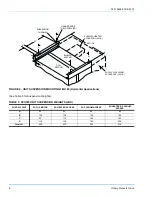
Page 5: ...bs Motor Drive 3 HP 90 5 HP 120 Electric Heat 10 KW 63 20 KW 66 126 30 KW 71 129 40 KW 132 50 KW 80 137 Supply Air Plenum 114 150 Return Air Grille 20 15 Base 100 120 1 Refer to Blower Motor and Drive Data table for more information TABLE 2 UNIT APPLICATION DATA APPLICATION LIMITATIONS MIN MAX Voltage Variation 208 230 3 60 1 187 253 Voltage Variation 460 3 60 1 414 506 Ambient Air on Outdoor Coil...

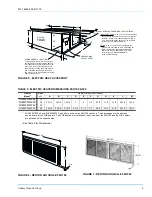
Page 6: ... BLOWER SECTION 5 A D SUSPENSION CHANNEL HANGER RODS FIELD SUPPLIED C B ELECTRIC HEATER ACCESSORY 40 Lb SUPPLY AIR PLENUM ACCESSORY 100 Lb D 58 11 16 55 TABLE 3 FEH180 UNIT SUSPENSION WEIGHTS LBS SUSP N POINT W 3 HP MOTOR W HEATER ACCESS W PLENUM ACCESS W HEATER PLENUM ACCESS A 95 95 85 85 B 120 120 100 100 C 95 115 165 185 D 115 140 185 205 Total Wt 425 470 535 575 ...

Page 7: ... BLOWER SECTION HEATING COIL SUSPENSION CHANNEL 43 3 4 5 A B C D E F 55 HANGER RODS FIELD SUPPLIED ELECTRIC HEAT ACCESS 40lbs each TABLE 4 FEH240 UNIT SUSPENSION WEIGHTS LBS SUSPENSION POINT W 5HP MOTOR1 1 Motor location at suspension point F W HEATER ACCESS A 142 142 B 132 132 C 152 152 D 162 189 E 132 158 F 127 154 Total Weight 847 927 ...

Page 8: ...ule Although the unit is always shipped in the vertical position with a vertical air dis charge as shown in a the blower module can be reposi tioned in the field as shown in illustrations b and c for maxi mum flexibility TheSupply Air Plenum Return Air Grille and Base accessories can be applied on arrangement a TheReturn Air Grille and Base accessories can be applied on arrangement b TheSupply Air...

Page 9: ... wire sizes up through 0 AWG 50 KW Add a 1 1 4 inch conduit fitting to the 1 23 32 inch hole for wire sizes up through 1 AWG Remove the knockout ring and add a two inches conduit fitting to the 2 1 2 hole for wire sizes up through 000 AWG Used on FEH180 only TABLE 5 ELECTRIC HEATER DIMENSIONS FEH180 240 Heater Model1 Nom kW Heater Dimensions inches A B C D E F G H K L M 2HB04501025 46 10 27 1 4 25...

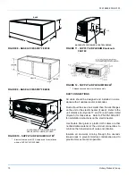
Page 10: ...he transmission of noise and vibration Insulate all ductwork running through the uncondi tioned areas to prevent moisture condensation and to provide more economical operation FIGURE 8 BASE ACCESSORY FEH180 FIGURE 9 BASE ACCESSORY FEH240 FIGURE 10 SUPPLY AIR PLENUM FEH 1801 1 Electric Heaters are NOT UL approved for installation within a SUPPLY AIR PLENUM 24 31 5 8 60 3 4 BASE 1 9 7 8 1 6 1 8 2 1 ...

Page 11: ...e matching outdoor unit for piping limitations line sizes and other design considerations INSTALLING REFRIGERANT MAINS The units are evacuated and dehydrated at the factory and shipped with a holding charge of Refrigerant 22 The vapor and liquid connections are sealed with cop per discs If the unit has already lost its holding charge it should be leak tested and the necessary repairs should be mad...

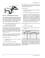
Page 12: ...llar the locking collar must be loosened to adjust the setting of the movable flange Note the following 1 The supply air CFM must be within the limitations shown in Tables 7 and 8 2 All pulleys can be adjusted in half turn increments 3 The tension on the belt should be adjusted for a deflection of 3 16 per foot of belt span with an applied force of 2 to 3 pounds This adjustment is made by moving t...

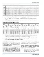
Page 13: ...g run 4 Knowing the pressure drop across a dry coil the actual CFM through the unit can be determined from the curve in Figure 16 If the CFM is above or below the specified value the supply air motor pulley may have to be re adjusted After one hour of operation check the belt and pulleys for tightness and alignment After readings have been obtained remove the tubes and seal up the drilled holes in...

Page 14: ...ntal configuration 2 Available static pressure in IWG to overcome the resistance of the duct system and any accessories added to the unit Refer to the respective tables for the resistance of these accessories and for additional motor and drive data 3 Motors can be selected to operate into their service factor because they are located in the moving airstream upstream of any heating device 4 kW is b...

Page 15: ...0 0 150 0 AWG 895 150 230 3 60 115 2 153 2 175 2 0 AWG 1073 150 460 3 60 57 6 76 6 80 4 AWG 1347 100 F1EH240A 5 20 KW 208 3 60 41 6 68 0 70 4 AWG 186 100 230 3 60 46 2 70 6 80 4 AWG 251 100 460 3 60 23 1 35 3 40 8 AWG 381 60 30 KW 208 3 60 62 5 94 1 100 3 AWG 233 100 230 3 60 69 3 99 4 100 3 AWG 315 100 460 3 60 34 6 49 7 50 8 AWG 381 60 40 KW 208 3 60 83 3 120 1 125 1 AWG 371 150 230 3 60 92 1 12...

Page 16: ...2 153 2 175 2 0 AWG 1073 150 460 3 60 57 6 76 6 80 4 AWG 1347 100 F1EH240A 5 20 KW 208 3 60 41 6 68 0 70 4 AWG 186 100 230 3 60 46 2 70 6 80 4 AWG 251 100 460 3 60 23 1 35 3 40 8 AWG 381 60 30 KW 208 3 60 62 5 94 1 100 3 AWG 233 100 230 3 60 69 3 99 4 100 3 AWG 315 100 460 3 60 34 6 49 7 50 8 AWG 381 60 40 KW 208 3 60 83 3 120 1 125 1 AWG 371 150 230 3 60 92 1 127 9 150 1 AWG 501 150 460 3 60 46 1...

Page 17: ...er motor are permanently lubricated and should not require any additional lubricant BELTS Maintain belt tension to extend belt life Replace the signs of failure begin to appear TABLE 11 TYPICAL FIELD WIRING Y1 W1 Y2 C R X O HC O HR G W1 Y2 Y1 R C X R C Y1 Y2 O W1 X G TB1 TB2 TERMINALS ON Supply Air Blower Motor Contactor 10M OR Terminal Block Electric Heat Control Box GROUND SCREW Heat Pump Only U...

Page 18: ...IMENSIONS ARE IN INCHES THEY ARE SUBJECT TO CHANGE WITHOUT NOTICE CERTIFIED DIMENSIONS WILL BE PROVIDED UPON REQUEST ACCESSORIES Electric Heaters Add 14 1 4 inches to unit height when using 10 20 30 or 50 kW heater Plenum Add 27 inches to overall unit height when used Base Add 24 inches to overall unit height when used 5 11 16 8 1 2 9 1 2 4 Ø 2 Ø 2 2 1 8 18 7 8 5 1 2 AIR OUT 5 7 8 19 3 8 21 7 8 60...

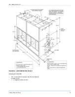
Page 19: ...035 16626 000 E 0103 Unitary Products Group 19 Clearances for FEH240 24 on one side for piping connection and access to blower motor 1 on opposite sides and rear FIGURE 18 UNIT DIMENSIONS FEH240 ...

Page 20: ...to change without notice Printed in U S A 035 16626 000 E 0103 Copyright by Unitary Products Group 2003 All rights reserved Supersedes 035 16626 000 D 0502 Unitary 5005 Norman Products York OK Group Drive 73069 ...

Reviews: