INSTALLATION GUIDE
PAGE
5
THERMAL BREAK
EXPANSION JOINT USED AS THERMAL BREAK
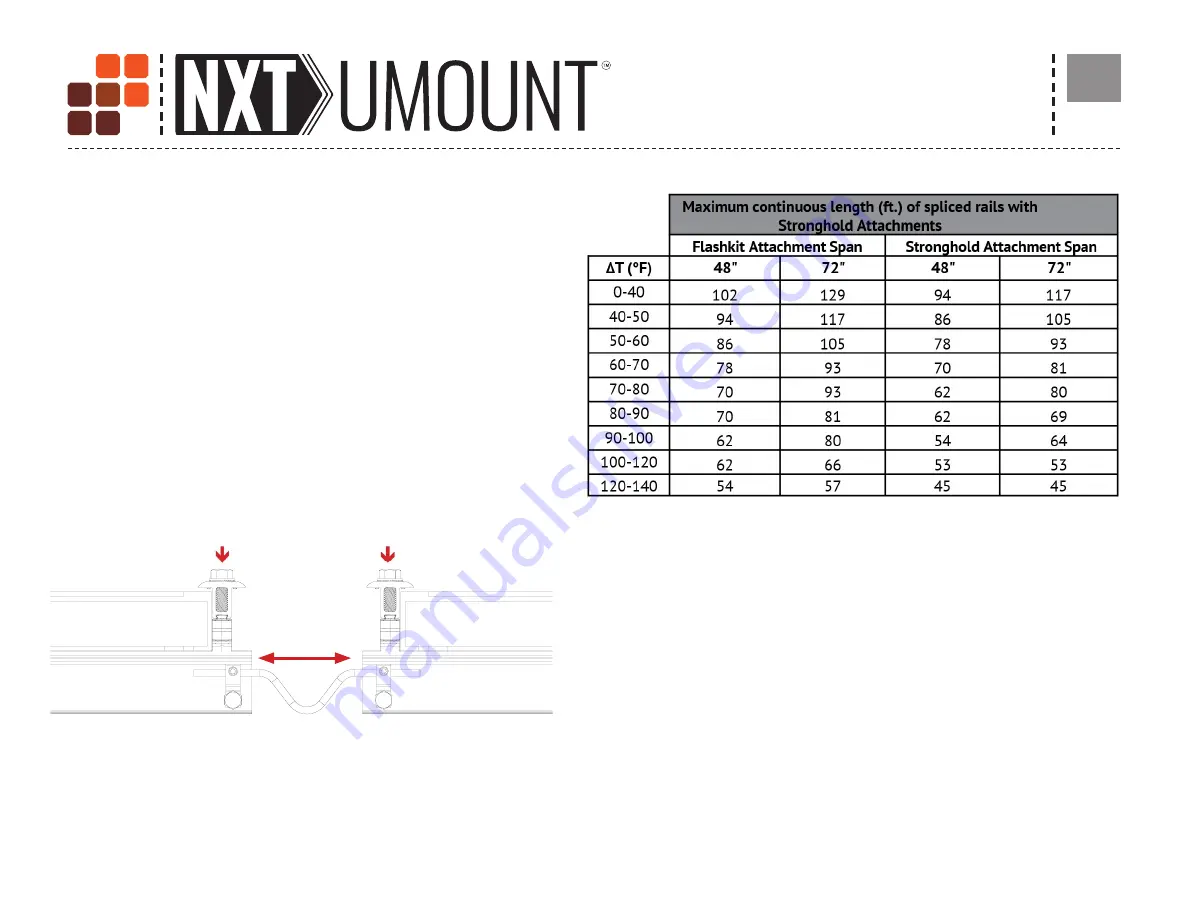
Expansion joints prevent buckling of rails or system connection failure
due to thermal expansion. Determine location of expansion joints prior to
installation of roof attachments and rails. To create a thermal expansion
joint, provide a sufficient gap between rails for proper installation of end
clamps and tooling to achieve required torque. A thermal break is required
when a continuous length of spliced rails exceeds the maximum allowable
lengths shown in the table to the right. For additional concerns on thermal
breaks in your specific project, please consult a licensed structural engineer.
Rails in expansion joint configurations are considered cantilevered and
must follow the cantilever rule on both sides of the expansion joint, which
states that the maximum amount of rail that can be cantilevered is 1/3 the
respective adjacent span. An expansion joint must not be spanned by a PV
module. Installing a module over an expansion joint would defeat the goal
of a thermal break and could result in damage to the array.
Bonding connection for splice used as a thermal break. Option shown uses
two Ilsco lugs (Model No. GBL-4DBT P/N GBL-4DBT - see product data sheet
for more details) and solid copper wire. Optional grounding may be achieved
through NXT UMOUNT MLPE & Lug Clamp. See Page 16.
The values displayed are the maximum allowed rail length, in feet, without a thermal
break. If your span is less than 48”, refer to the NXT UMOUNT Design & Engineering
Guide for max lengths of continuous rail before a thermal break is required.
Determine the maximum rail temperature difference (ΔT) between the time of
installation and the extreme high or low temperature. The Extreme Annual Design
Conditions table at the following URL can be used as a reference when determining
ΔT.
http://ashrae-meteo.info/
. The installer is responsible for determining the
maximum temperature difference (ΔT) used to establish the maximum rail length.
As spans increase, so does the maximum reaction force that the rail exerts on
the L-foot. Ensuring that the Maximum Reaction Forces do not exceed the shear
capacity of the roof connection. See NXT UMOUNT Design & Engineering Guide for
corresponding reaction forces.
Provide a sufficient gap between rails for proper installation of end
clamps and tooling
Connect rails with the bonding wire.
,
Install end clamps.
See Page 19.


